ESP32-Based Smart Agriculture Monitoring System with RS485 Communication
Circuit Documentation
Summary
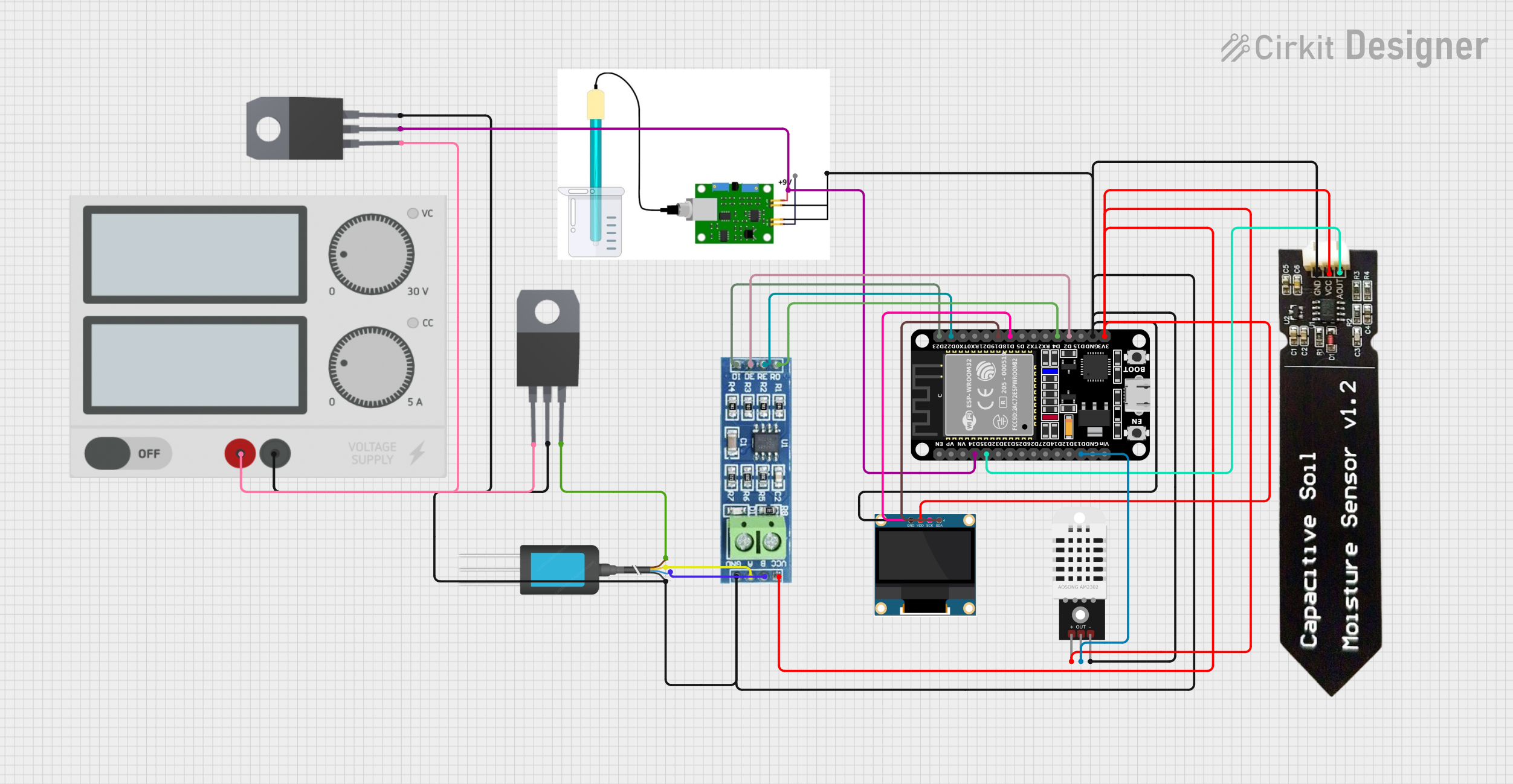
The circuit in question is designed to interface various sensors and modules with an ESP32 microcontroller for the purpose of monitoring environmental parameters. The sensors include a DHT22 for temperature and humidity, a pH sensor for measuring the acidity or alkalinity of a solution, an NPK soil sensor for detecting the levels of nitrogen, phosphorus, and potassium in soil, and a capacitive soil moisture sensor. Additionally, an RS485 transceiver is used for long-distance communication, and a 0.96" OLED display is included for data visualization. The circuit is powered by a power supply unit, and voltage regulation is provided by two 7808 voltage regulators.
Component List
DHT22
- Temperature and humidity sensor
- Pins:
+,Out,-
pH Sensor
- Sensor for measuring the acidity or alkalinity of a solution
- Pins:
+9volt,output pin,GND
NPK Soil Sensor
- Sensor for detecting the levels of nitrogen, phosphorus, and potassium in soil
- Pins:
12V DC,A,B,GND
ESP32 (30 pin)
- Microcontroller with WiFi and Bluetooth capabilities
- Pins:
EN,VP,VN,D34,D35,D32,D33,D25,D26,D27,D14,D12,D13,GND,Vin,D23,D22,TX0,RX0,D21,D19,D18,D5,TX2,RX2,D4,D2,D15,3V3
Capacitive Soil Moisture Sensor V1.2
- Sensor for measuring the moisture content in soil
- Pins:
GND,VCC,AOUT
RS485 Transceiver
- Module for long-distance communication
- Pins:
VCC,RO,RE,GND,B,A,DE,DI
0.96" OLED Display
- Small display for data visualization
- Pins:
GND,VDD,SCK,SDA
7808 Voltage Regulator
- Provides regulated +8V output
- Pins:
INPUT,GND,OUTPUT
Power Supply
- Provides power to the circuit
- Pins:
+,-
Wiring Details
DHT22
+to ESP323V3Outto ESP32D13-to GND
pH Sensor
+9voltto ESP32D34output pin(not connected)GNDto GND
NPK Soil Sensor
12V DCto 7808OUTPUTAto RS485ABto RS485BGNDto GND
ESP32 (30 pin)
D34to pH Sensor+9voltD35to Capacitive Soil Moisture SensorAOUTD13to DHT22OutD23to RS485DID22to RS485RED19to OLEDSDAD18to OLEDSCKD4to RS485ROD2to RS485DE3V3to DHT22+, Capacitive Soil Moisture SensorVCC, RS485VCC, OLEDVDDGNDto GND
Capacitive Soil Moisture Sensor V1.2
AOUTto ESP32D35VCCto ESP323V3GNDto GND
RS485 Transceiver
DIto ESP32D23REto ESP32D22ROto ESP32D4DEto ESP32D2Ato NPK Soil SensorABto NPK Soil SensorBVCCto ESP323V3GNDto GND
0.96" OLED Display
GNDto GNDVDDto ESP323V3SCKto ESP32D18SDAto ESP32D19
7808 Voltage Regulator
INPUTto Power Supply+GNDto GNDOUTPUTto NPK Soil Sensor12V DC
Power Supply
+to 7808INPUT-to GND
Ground Connections
All GND pins are interconnected and connected to the Power Supply -.
Code Documentation
No code has been provided for the microcontrollers in the circuit. When code is available, it should be documented here with explanations for each function and routine, including setup and loop functions for the ESP32 microcontroller, as well as any interrupt service routines or peripheral configurations.
Please note that the above documentation is based on the provided information and assumes that the circuit is correctly designed for the intended functionality. It is recommended to review the actual circuit and test it to ensure that it operates as expected.