
Circuit Documentation
Summary of the Circuit
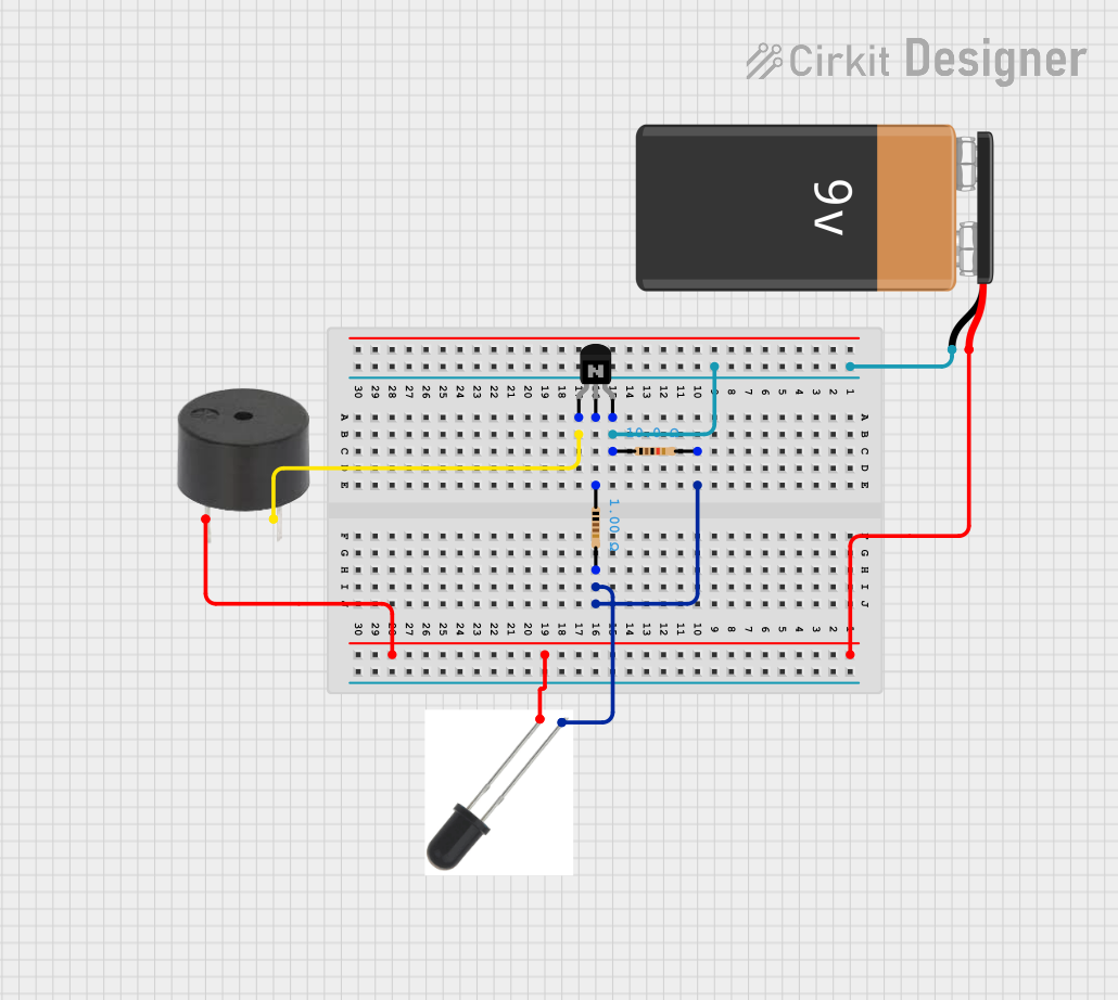
The circuit described by the provided inputs appears to be a simple control circuit that uses an NPN transistor to drive a buzzer, with the transistor being controlled by a resistor network. The circuit is powered by a 9V battery. There is no microcontroller code provided, indicating that this circuit operates purely on the analog domain without any programmable digital control.
Component List
NPN Transistor (EBC)
- Description: A standard NPN bipolar junction transistor with three pins: emitter, base, and collector.
- Purpose: Acts as a switch or amplifier in the circuit.
Resistor (10 Ohms)
- Description: A passive two-terminal electrical component that implements electrical resistance as a circuit element.
- Purpose: Limits the current flowing through the circuit or divides voltage.
Resistor (1 Ohm)
- Description: Another resistor with a different resistance value.
- Purpose: Provides a precise current to the base of the NPN transistor.
Buzzer
- Description: An electromechanical component that emits sound when an electrical signal is applied.
- Purpose: Acts as an output device to provide an audible alert or signal.
9V Battery
- Description: A standard 9-volt battery with a positive and a negative terminal.
- Purpose: Provides the power source for the circuit.
Wiring Details
NPN Transistor (EBC)
- Emitter connected to the buzzer's GND pin.
- Base connected to one pin of the 1 Ohm resistor.
- Collector connected to one pin of the 10 Ohms resistor and the negative terminal of the 9V battery.
Resistor (10 Ohms)
- One pin connected to the collector of the NPN transistor and the negative terminal of the 9V battery.
- The other pin connected to the 1 Ohm resistor and an unidentified component labeled "f".
Resistor (1 Ohm)
- One pin connected to the base of the NPN transistor.
- The other pin connected to the 10 Ohms resistor and the unidentified component labeled "f".
Buzzer
- PIN connected to the positive terminal of the 9V battery and the unidentified component labeled "f".
- GND connected to the emitter of the NPN transistor.
9V Battery
- + (positive terminal) connected to the buzzer's PIN and the unidentified component labeled "f".
- - (negative terminal) connected to the collector of the NPN transistor and one pin of the 10 Ohms resistor.
Documented Code
No code has been provided for any microcontrollers in the circuit. This section is not applicable for the current documentation.
Please note that the component labeled "f" is unidentified in the provided parts list and does not have a clear purpose or connection details beyond what is listed in the wiring details. Further clarification on this component would be necessary for a complete understanding of the circuit's functionality.