Wi-Fi Controlled RGB LED Strip with ESP32 and MOSFETs
Circuit Documentation
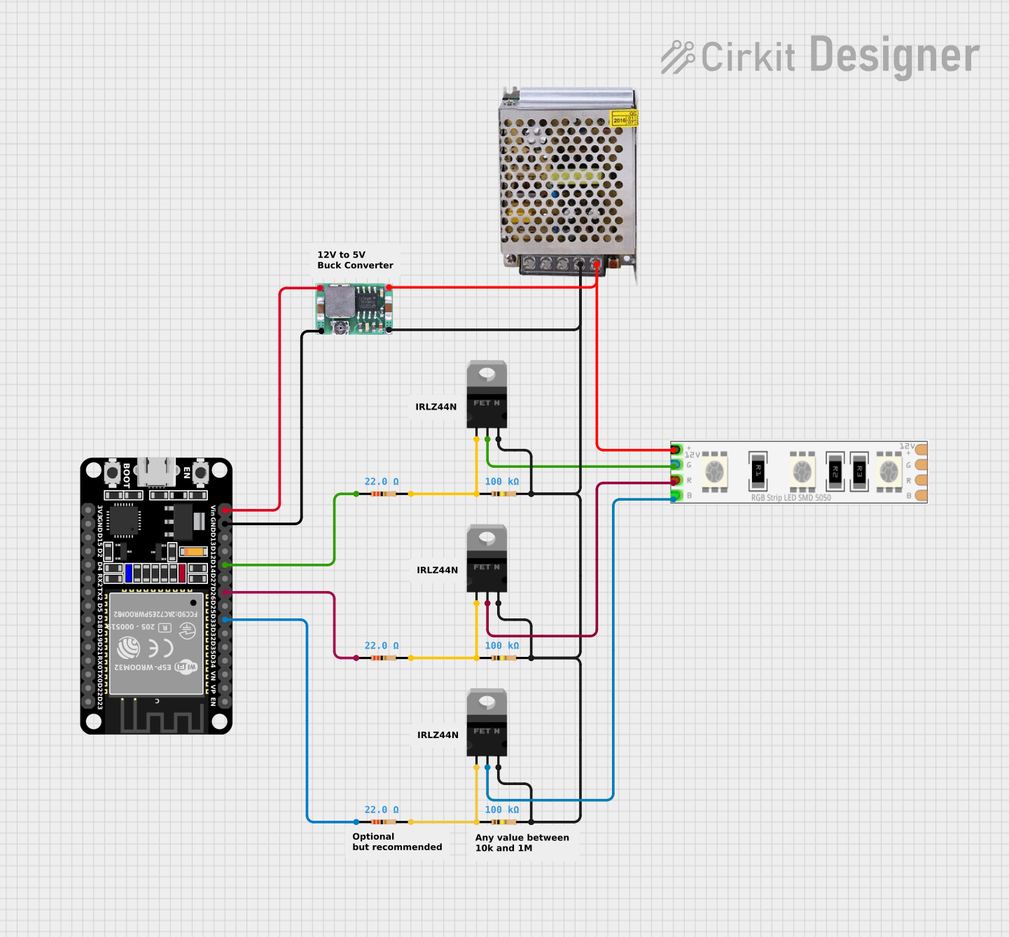
Summary
This circuit is designed to control a 12V RGB LED strip using an ESP32 microcontroller and nMOS transistors (MOSFETs). The ESP32 can individually control the red (R), green (G), and blue (B) channels of the LED strip by sending PWM signals to the gates of the MOSFETs, which in turn switch the corresponding color channels on the LED strip. The power supply provides 12V to the LED strip and also powers the ESP32 through a Mini-360 DC-DC Step Down Buck Converter, which steps down the voltage to a suitable level for the microcontroller. The circuit includes resistors for gate pull-down and current limiting purposes.
Component List
- 12V RGB LED Strip: A strip of LEDs that can display multiple colors by mixing red, green, and blue light.
- nMOS Transistor (MOSFET): Used as a switch to control the current flow to each color channel of the LED strip.
- Resistor: Various resistors are used in the circuit for current limiting and to pull down the gate of the MOSFETs.
- POWER SUPPLY 12V 5AMP: Provides the necessary power to the LED strip and the rest of the circuit.
- ESP32 (30 pin): A microcontroller with WiFi capabilities that is used to control the MOSFETs and, by extension, the LED strip.
- Mini-360 DC-DC Step Down Buck Converter: Steps down the voltage from 12V to a lower voltage suitable for the ESP32.
Wiring Details
12V RGB LED Strip
- 12v +: Connected to the 12V output of the power supply.
- G: Connected to the drain of an nMOS transistor.
- R: Connected to the drain of another nMOS transistor.
- B: Connected to the drain of a third nMOS transistor.
nMOS Transistor (MOSFET)
- gate: Connected to an ESP32 GPIO pin through a resistor (for gate control).
- drain: Connected to the corresponding color channel on the RGB LED strip.
- source: Connected to the ground (GND) of the power supply.
Resistor
- Used for pulling down the gate of the MOSFETs and limiting current to the gates from the ESP32 GPIO pins.
POWER SUPPLY 12V 5AMP
- 12V-24V Output (DC): Provides power to the RGB LED strip and the input of the Mini-360 DC-DC Step Down Buck Converter.
- GND (DC): Common ground for the circuit.
ESP32 (30 pin)
- D14, D26, D33: GPIO pins used to control the gates of the MOSFETs through resistors.
- GND: Connected to the ground of the Mini-360 DC-DC Step Down Buck Converter.
- Vin: Connected to the output of the Mini-360 DC-DC Step Down Buck Converter.
Mini-360 DC-DC Step Down Buck Converter
- Input +: Connected to the 12V output of the power supply.
- Input -: Connected to the ground (GND) of the power supply.
- Output +: Connected to the Vin pin of the ESP32.
- Output -: Connected to the GND pin of the ESP32.
Documented Code
There is no code provided for the ESP32 microcontroller. The code would typically include the initialization of the GPIO pins as outputs and the generation of PWM signals to control the brightness of each color channel on the RGB LED strip.