Cirkit Designer
Your all-in-one circuit design IDE
Home /
Project Documentation
STM32F103C8T6 Battery-Powered LED Indicator Circuit
Circuit Documentation
Summary
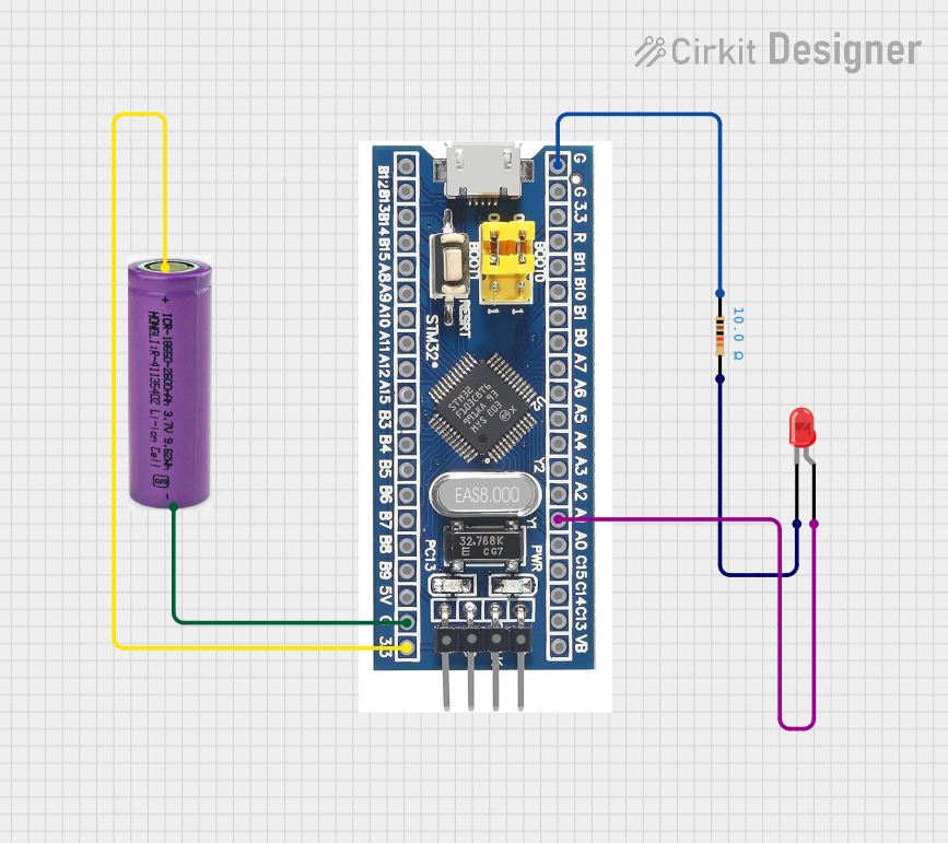
This document provides a detailed overview of a simple circuit involving an STM32F103C8T6 microcontroller, a red LED, a resistor, and a 3.3V battery. The circuit is designed to power the microcontroller and control the LED.
Component List
STM32F103C8T6
- Description: A 32-bit ARM Cortex-M3 microcontroller.
- Pins: GND, 3.3V, reset, B11, B10, B1, B0, A7, A6, A5, A4, A3, A2, A1, A0, C15, C14, C13, VBT, 3.3, 5V, B12, B13, b14, B15, A8, A9, A10, A11, A12, A15, B3, B4, B5, B6, B7, B8, B9, SWIO, SWCLK
- Purpose in Circuit: Main controller for the circuit.
LED: Two Pin (red)
- Description: A red LED with two pins.
- Pins: cathode, anode
- Purpose in Circuit: Visual indicator controlled by the microcontroller.
Resistor
- Description: A resistor with a resistance of 10 Ohms.
- Pins: pin1, pin2
- Properties:
- Resistance: 10 Ohms
- Purpose in Circuit: Current limiting for the LED.
3.3V Battery
- Description: A 3.3V battery.
- Pins: +, -
- Purpose in Circuit: Power supply for the circuit.
Wiring Details
STM32F103C8T6
- GND is connected to pin1 of the Resistor.
- A1 is connected to the anode of the LED.
- 3.3 is connected to the + of the 3.3V Battery.
- GND is connected to the - of the 3.3V Battery.
LED: Two Pin (red)
- anode is connected to A1 of the STM32F103C8T6.
- cathode is connected to pin2 of the Resistor.
Resistor
- pin1 is connected to GND of the STM32F103C8T6.
- pin2 is connected to the cathode of the LED.
3.3V Battery
- + is connected to 3.3 of the STM32F103C8T6.
- - is connected to GND of the STM32F103C8T6.
Code
There is no code provided for this circuit.
This document provides a comprehensive overview of the circuit, including a summary, detailed component descriptions, wiring details, and code documentation.