
Arduino Nano OBD-II Data Logger with TFT Display and CAN Bus Interface
View and Edit Project In Cirkit Designer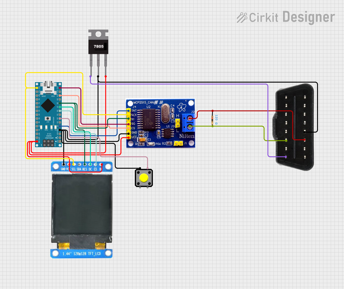
Circuit Documentation
Summary
This circuit integrates an Arduino Nano microcontroller with an MCP2515 CAN controller, a 7805 voltage regulator, an ST7735 TFT display, a pushbutton, a resistor, and an OBD-II port. The circuit is designed to interface with a vehicle's OBD-II port, display information on the TFT screen, and allow user interaction through the pushbutton.
Component List
Arduino Nano
- Description: A small, complete, and breadboard-friendly board based on the ATmega328P.
- Pins: D1/TX, D0/RX, RESET, GND, D2, D3, D4, D5, D6, D7, D8, D9, D10, D11/MOSI, D12/MISO, VIN, 5V, A7, A6, A5, A4, A3, A2, A1, A0, AREF, 3V3, D13/SCK
MCP2515
- Description: A CAN controller with SPI interface.
- Pins: INT, SCK, SI, SO, CS, GND, VCC, H, L
7805
- Description: A voltage regulator that outputs a stable 5V.
- Pins: Vin, Gnd, Vout
ST7735 128x128 1.44 TFT I2C Color
- Description: A 1.44-inch TFT display with I2C interface.
- Pins: BL, C5, DC, RES, SDA, SCL, GND, VCC
Resistor
- Description: A 120 Ohm resistor.
- Pins: pin1, pin2
- Properties: Resistance: 120 Ohms
OBD-II port
- Description: A standard OBD-II port for vehicle diagnostics.
- Pins: 12v, GND, CANH, CANL
Pushbutton
- Description: A simple pushbutton for user input.
- Pins: Pin 2, Pin 1, Pin 3, Pin 4
Wiring Details
Arduino Nano
- GND connected to the common ground.
- D2 connected to INT of MCP2515.
- D4 connected to Pin 4 of Pushbutton.
- D6 connected to C5 of ST7735 TFT.
- D7 connected to DC of ST7735 TFT.
- D8 connected to RES of ST7735 TFT and SI of MCP2515.
- D10 connected to CS of MCP2515.
- D12/MISO connected to SO of MCP2515.
- D13/SCK connected to SCK of MCP2515 and SCL of ST7735 TFT.
- VIN connected to Vout of 7805.
MCP2515
- GND connected to the common ground.
- INT connected to D2 of Arduino Nano.
- SCK connected to D13/SCK of Arduino Nano and SCL of ST7735 TFT.
- SI connected to RES of ST7735 TFT and D8 of Arduino Nano.
- SO connected to D12/MISO of Arduino Nano.
- CS connected to D10 of Arduino Nano.
- VCC connected to Vout of 7805.
- H connected to CANH of OBD-II port and pin1 of Resistor.
- L connected to CANL of OBD-II port and pin2 of Resistor.
7805
- Gnd connected to the common ground.
- Vout connected to VCC of MCP2515, BL and VCC of ST7735 TFT, and VIN of Arduino Nano.
- Vin connected to 12v of OBD-II port.
ST7735 128x128 1.44 TFT I2C Color
- GND connected to the common ground.
- BL connected to Vout of 7805.
- C5 connected to D6 of Arduino Nano.
- DC connected to D7 of Arduino Nano.
- RES connected to SI of MCP2515 and D8 of Arduino Nano.
- SDA not connected.
- SCL connected to SCK of MCP2515 and D13/SCK of Arduino Nano.
- VCC connected to Vout of 7805.
Resistor
- pin1 connected to CANH of OBD-II port and H of MCP2515.
- pin2 connected to CANL of OBD-II port and L of MCP2515.
OBD-II port
- GND connected to the common ground.
- 12v connected to Vin of 7805.
- CANH connected to H of MCP2515 and pin1 of Resistor.
- CANL connected to L of MCP2515 and pin2 of Resistor.
Pushbutton
- Pin 1 connected to the common ground.
- Pin 4 connected to D4 of Arduino Nano.
Documented Code
Arduino Nano Code (sketch.ino)
void setup() {
  // put your setup code here, to run once:

}

void loop() {
  // put your main code here, to run repeatedly:

}
Additional Documentation (documentation.txt)
This documentation provides a comprehensive overview of the circuit, including a detailed component list, wiring details, and the code used in the Arduino Nano microcontroller.