
ESP32-CAM Controlled Servo Array with IR Sensing and OLED Feedback
View and Edit Project In Cirkit Designer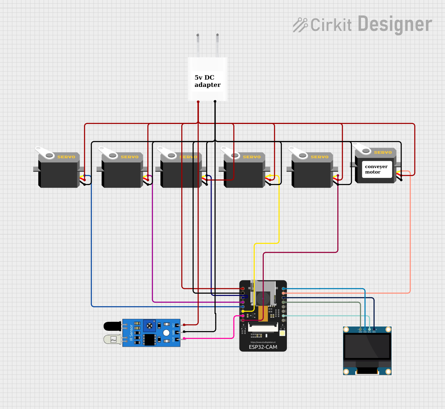
Circuit Documentation
Summary of the Circuit
The circuit in question appears to be designed for controlling multiple servo motors, interfacing with an IR sensor, and displaying information on an OLED screen, all managed by an ESP32-CAM microcontroller. The 5V Adapter provides power to the components. The ESP32-CAM is responsible for processing inputs from the IR sensor and controlling the servo motors based on the logic defined in the microcontroller's code. The OLED screen is likely used to display status information or readings from the IR sensor.
Component List
Servo Motors
- Description: Servo motors are used for precise control of angular or linear position, velocity, and acceleration. They are commonly used in robotics, manufacturing, and remote control applications.
- Purpose: In this circuit, the servo motors are likely used for movement or positioning tasks, controlled by the ESP32-CAM.
IR Sensor
- Description: An IR sensor is used to detect obstacles or measure distances using infrared light.
- Purpose: The IR sensor in this circuit is likely used for detecting objects or changes in the environment.
0.96" OLED
- Description: A small OLED display capable of showing graphics and text.
- Purpose: The OLED is used to display information such as sensor readings or system status.
5V Adapter
- Description: A power supply module that converts AC power to 5V DC power.
- Purpose: It provides the necessary power to the components in the circuit.
ESP32 - CAM
- Description: A small camera module with Wi-Fi capability that also serves as a microcontroller.
- Purpose: It is the central processing unit of the circuit, handling sensor data, controlling the servos, and managing the OLED display.
Wiring Details
Servo Motors
- Ground (GND): Connected to the ground pin of the 5V Adapter.
- Power (VCC): Connected to the 5V output of the 5V Adapter.
- Control (Pulse): Each servo has its control pin connected to a designated GPIO on the ESP32-CAM for individual control.
IR Sensor
- Output (Out): Connected to a GPIO on the ESP32-CAM for reading sensor data.
- Ground (GND): Connected to the ground pin of the 5V Adapter.
- Power (VCC): Connected to the 5V output of the 5V Adapter.
0.96" OLED
- Serial Clock (SCK): Connected to the corresponding SCK pin on the ESP32-CAM for SPI communication.
- Serial Data (SDA): Connected to the corresponding SDA pin on the ESP32-CAM for SPI communication.
- Ground (GND): Connected to the ground pin of the 5V Adapter.
- Power (VDD): Connected to the 3.3V output of the ESP32-CAM.
5V Adapter
- AC In: Accepts AC input to be converted to 5V DC.
- 5V Output: Provides power to the servos, IR sensor, and ESP32-CAM.
- Ground (GND): Common ground for the circuit.
ESP32 - CAM
- 5V: Receives power from the 5V Adapter.
- Ground (GND): Common ground for the circuit.
- GPIOs (IO12, IO13, IO14, IO15, IO2, IO4, IO0, IO16): Used for controlling servos, reading IR sensor data, and communicating with the OLED.
- Voltage Output (VOT): Connected to the SCK pin of the OLED for SPI communication.
- Voltage Reference (VOR): Not used in this circuit.
- Voltage Input (VCC): Not used in this circuit as power is provided through the 5V pin.
- 3.3V: Provides power to the OLED display.
Documented Code
Since no code was provided in the input, this section cannot be completed. Normally, this section would include the source code for the microcontroller, with comments explaining the functionality of each part of the code, such as initialization, main loop, interrupt service routines, and any functions for handling peripherals like sensors and displays.