Cirkit Designer
Your all-in-one circuit design IDE
Home /
Project Documentation
Arduino UNO Controlled Dual Stepper Motor and IR Sensor System with 12V Power Supply
Circuit Documentation
Summary
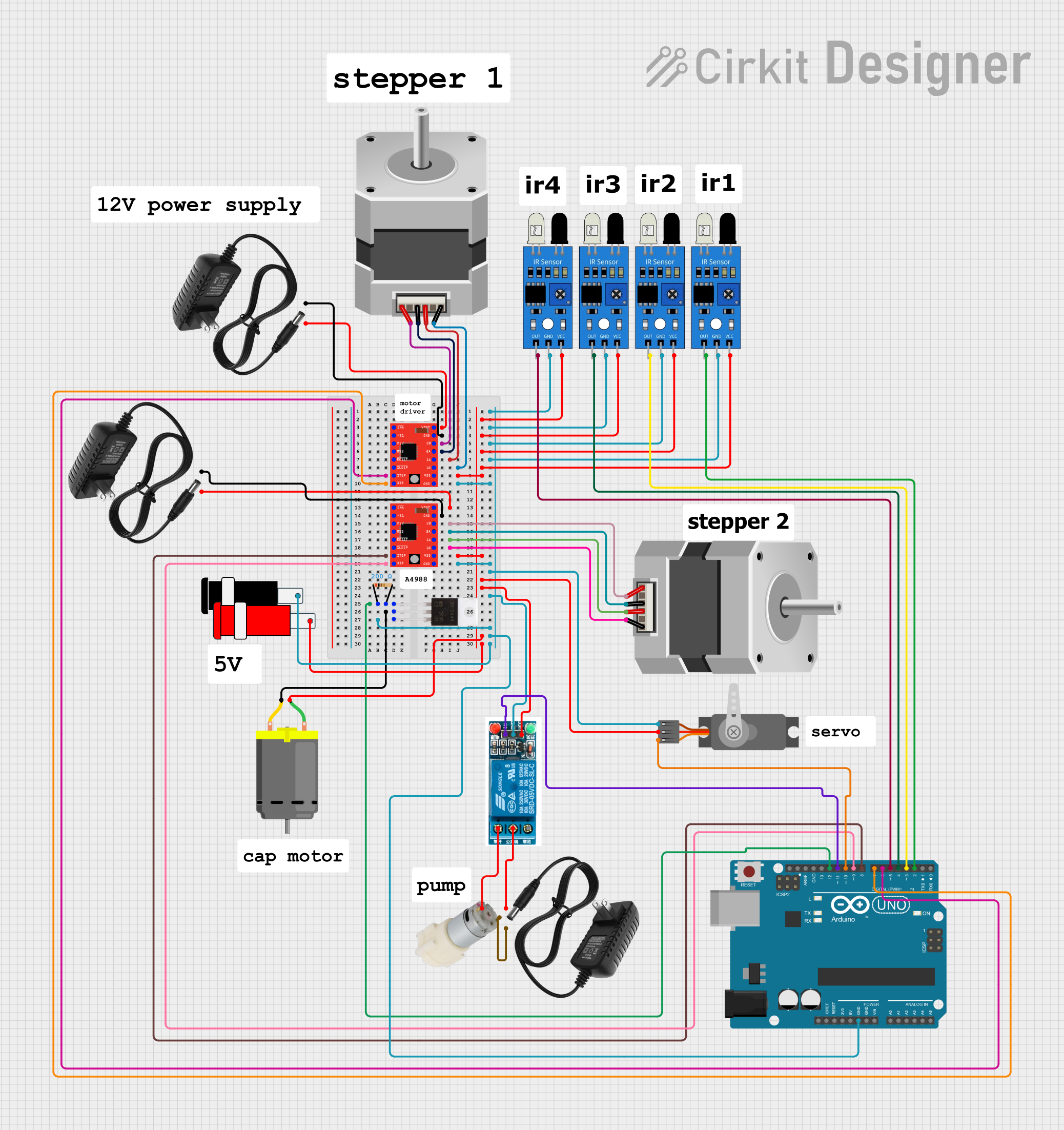
This circuit involves an Arduino UNO microcontroller interfacing with various components including stepper motors, IR sensors, a DC motor, a servo motor, a water pump, and a relay. The circuit is designed to control these components based on sensor inputs and programmed logic.
Component List
Stepper Motor (Bipolar)
- Pins: D, B, C, A
- Description: A bipolar stepper motor used for precise control of rotational position.
IR Sensor
- Pins: out, gnd, vcc
- Description: Infrared sensor used for detecting objects or distance.
Arduino UNO
- Pins: UNUSED, IOREF, Reset, 3.3V, 5V, GND, Vin, A0, A1, A2, A3, A4, A5, SCL, SDA, AREF, D13, D12, D11, D10, D9, D8, D7, D6, D5, D4, D3, D2, D1, D0
- Description: A microcontroller board based on the ATmega328P.
DC Motor
- Pins: pin 1, pin 2
- Description: A simple DC motor for rotational motion.
Servo (Wokwi Compatible)
- Pins: GND, V+, PWM
- Description: A servo motor for precise control of angular position.
A4988 Stepper Motor Driver (Red)
- Pins: ENABLE, MS1, MS2, MS3, RESET, SLEEP, STEP, DIR, VMOT, GND, 2B, 2A, 1A, 1B, VDD
- Description: A driver for controlling bipolar stepper motors.
IRFZ44N
- Pins: Gate, Drain, Source
- Description: A power MOSFET used for switching applications.
Resistor
- Pins: pin1, pin2
- Description: A resistor with a resistance of 200 Ohms.
Connector 5V
- Pins: GND, VCC
- Description: A connector for 5V power supply.
12V Power Supply
- Pins: +, -
- Description: A power supply providing 12V.
Water Pump 12V
- Pins: +, -
- Description: A 12V water pump.
5V Relay
- Pins: Normally Open, Common terminal, Normally Closed, In, GND, VCC
- Description: A relay for switching high power devices.
Wiring Details
Stepper Motor (Bipolar)
Motor 1
- Pin A: Connected to 2B of A4988 Stepper Motor Driver
- Pin C: Connected to 2A of A4988 Stepper Motor Driver
- Pin B: Connected to 1A of A4988 Stepper Motor Driver
- Pin D: Connected to 1B of A4988 Stepper Motor Driver
Motor 2
- Pin A: Connected to 2B of A4988 Stepper Motor Driver
- Pin C: Connected to 2A of A4988 Stepper Motor Driver
- Pin B: Connected to 1A of A4988 Stepper Motor Driver
- Pin D: Connected to 1B of A4988 Stepper Motor Driver
IR Sensor
Sensor 1
- Pin vcc: Connected to VDD of A4988 Stepper Motor Driver
- Pin gnd: Connected to GND of A4988 Stepper Motor Driver
- Pin out: Connected to D5 of Arduino UNO
Sensor 2
- Pin vcc: Connected to VDD of A4988 Stepper Motor Driver
- Pin gnd: Connected to GND of A4988 Stepper Motor Driver
- Pin out: Connected to D2 of Arduino UNO
Sensor 3
- Pin vcc: Connected to VDD of A4988 Stepper Motor Driver
- Pin gnd: Connected to GND of A4988 Stepper Motor Driver
- Pin out: Connected to D3 of Arduino UNO
Sensor 4
- Pin vcc: Connected to VDD of A4988 Stepper Motor Driver
- Pin gnd: Connected to GND of A4988 Stepper Motor Driver
- Pin out: Connected to D4 of Arduino UNO
Arduino UNO
- Pin D6: Connected to STEP of A4988 Stepper Motor Driver
- Pin D7: Connected to DIR of A4988 Stepper Motor Driver
- Pin D8: Connected to STEP of A4988 Stepper Motor Driver
- Pin D9: Connected to DIR of A4988 Stepper Motor Driver
- Pin D10: Connected to PWM of Servo
- Pin D11: Connected to In of 5V Relay
- Pin D12: Connected to pin2 of Resistor
- Pin GND: Connected to GND of A4988 Stepper Motor Driver
DC Motor
- Pin 1: Connected to VCC of Connector 5V
- Pin 2: Connected to Drain of IRFZ44N
Servo (Wokwi Compatible)
- Pin V+: Connected to VCC of Connector 5V
- Pin GND: Connected to GND of Connector 5V
- Pin PWM: Connected to D10 of Arduino UNO
A4988 Stepper Motor Driver (Red)
Driver 1
- Pin VMOT: Connected to + of 12V Power Supply
- Pin GND: Connected to - of 12V Power Supply
- Pin STEP: Connected to D6 of Arduino UNO
- Pin DIR: Connected to D7 of Arduino UNO
- Pin VDD: Connected to VDD of A4988 Stepper Motor Driver
- Pin 2B: Connected to A of Stepper Motor
- Pin 2A: Connected to C of Stepper Motor
- Pin 1A: Connected to B of Stepper Motor
- Pin 1B: Connected to D of Stepper Motor
Driver 2
- Pin VMOT: Connected to + of 12V Power Supply
- Pin GND: Connected to - of 12V Power Supply
- Pin STEP: Connected to D8 of Arduino UNO
- Pin DIR: Connected to D9 of Arduino UNO
- Pin VDD: Connected to VDD of A4988 Stepper Motor Driver
- Pin 2B: Connected to A of Stepper Motor
- Pin 2A: Connected to C of Stepper Motor
- Pin 1A: Connected to B of Stepper Motor
- Pin 1B: Connected to D of Stepper Motor
IRFZ44N
- Pin Gate: Connected to pin1 of Resistor
- Pin Drain: Connected to pin 2 of DC Motor
- Pin Source: Connected to GND of A4988 Stepper Motor Driver
Resistor
- Pin pin1: Connected to Gate of IRFZ44N
- Pin pin2: Connected to D12 of Arduino UNO
Connector 5V
- Pin VCC: Connected to VCC of A4988 Stepper Motor Driver
- Pin GND: Connected to GND of A4988 Stepper Motor Driver
12V Power Supply
- Pin +: Connected to VMOT of A4988 Stepper Motor Driver
- Pin -: Connected to GND of A4988 Stepper Motor Driver
Water Pump 12V
- Pin +: Connected to Normally Open of 5V Relay
- Pin -: Connected to - of 12V Power Supply
5V Relay
- Pin Normally Open: Connected to + of Water Pump 12V
- Pin Common terminal: Connected to + of 12V Power Supply
- Pin In: Connected to D11 of Arduino UNO
- Pin GND: Connected to GND of Connector 5V
- Pin VCC: Connected to VCC of Connector 5V
Documented Code
Arduino UNO Code
void setup() {
  // put your setup code here, to run once:

}

void loop() {
  // put your main code here, to run repeatedly:

}
This code is a basic template for the Arduino UNO. The setup() function is where you initialize your components, and the loop() function is where you place the main logic that runs repeatedly.