
ESP8266 NodeMCU Environment Monitoring System with Stepper Motor and Sensors
View and Edit Project In Cirkit Designer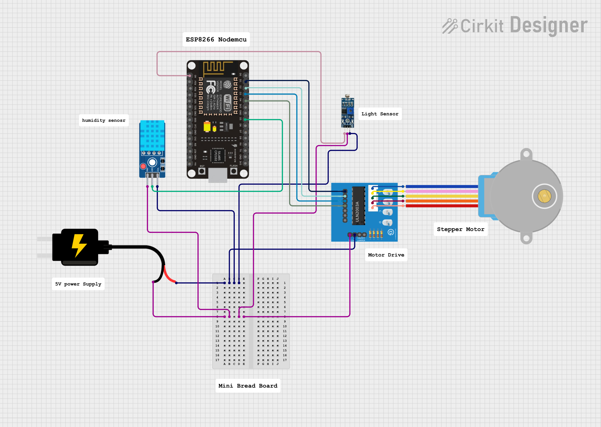
Circuit Documentation
Summary
This document provides a detailed overview of a circuit designed to monitor environmental conditions using an ESP8266 NodeMCU microcontroller. The circuit includes a DHT11 sensor for temperature and humidity measurements, an LDR module for light intensity detection, and a 28BYJ-48 stepper motor controlled via a ULN2003A driver. The microcontroller processes the sensor data and can control the stepper motor based on the readings.
Component List
ESP8266 NodeMCU
- Description: A low-cost Wi-Fi microcontroller with multiple GPIO pins.
- Pins: D0, D1, D2, D3, D4, 3V3, GND, D5, D6, D7, D8, RX, TX, A0, RSV, SD3, SD2, SD1, CMD, SD0, CLK, EN, RST, VIN
28BYJ-48 Stepper Motor
- Description: A small, inexpensive stepper motor commonly used in various applications.
- Pins: BLUE, PINK, YELLOW, ORANGE, RED
ULN2003A Breakout Board
- Description: A driver board for controlling the 28BYJ-48 stepper motor.
- Pins: In 1, In 2, In 3, In 4, In 5, In 6, In 7, 0V, +5V, ON/OFF jumper switch, BLUE wire, PINK wire, YELLOW wire, ORANGE wire, RED wire
LDR Module 3 Pin
- Description: A light-dependent resistor module for measuring light intensity.
- Pins: VCC, GND, DO
DHT11 Sensor V2
- Description: A digital temperature and humidity sensor.
- Pins: GND, DAT, VCC
DC Source 5V
- Description: A 5V DC power source.
- Pins: VCC, GND
Wiring Details
ESP8266 NodeMCU
- D1 connected to In 1 of ULN2003A Breakout Board
- D2 connected to In 2 of ULN2003A Breakout Board
- D3 connected to In 3 of ULN2003A Breakout Board
- D4 connected to In 4 of ULN2003A Breakout Board
- D5 connected to DAT of DHT11 Sensor V2
- A0 connected to DO of LDR Module 3 Pin
28BYJ-48 Stepper Motor
- BLUE connected to BLUE wire of ULN2003A Breakout Board
- PINK connected to PINK wire of ULN2003A Breakout Board
- YELLOW connected to YELLOW wire of ULN2003A Breakout Board
- ORANGE connected to ORANGE wire of ULN2003A Breakout Board
- RED connected to RED wire of ULN2003A Breakout Board
ULN2003A Breakout Board
- In 1 connected to D1 of ESP8266 NodeMCU
- In 2 connected to D2 of ESP8266 NodeMCU
- In 3 connected to D3 of ESP8266 NodeMCU
- In 4 connected to D4 of ESP8266 NodeMCU
- 0V connected to GND of DC Source 5V
- +5V connected to VCC of DC Source 5V
LDR Module 3 Pin
- VCC connected to VCC of DC Source 5V
- GND connected to GND of DC Source 5V
- DO connected to A0 of ESP8266 NodeMCU
DHT11 Sensor V2
- VCC connected to VCC of DC Source 5V
- GND connected to GND of DC Source 5V
- DAT connected to D5 of ESP8266 NodeMCU
DC Source 5V
- VCC connected to VCC of DHT11 Sensor V2, LDR Module 3 Pin, and +5V of ULN2003A Breakout Board
- GND connected to GND of DHT11 Sensor V2, LDR Module 3 Pin, and 0V of ULN2003A Breakout Board
Code Documentation
/*
 * ESP8266 NodeMCU Controlled Environment Monitoring System
 * with Stepper Motor and Sensors
 *
 * This code controls a stepper motor using a ULN2003A driver, reads data from
 * a DHT11 temperature and humidity sensor, and an LDR module for light
 * intensity. The data is processed and can be used for various applications
 * such as controlling the environment based on sensor readings.
 */

#include <DHT.h>

// Pin definitions
#define DHTPIN D5
#define DHTTYPE DHT11
#define LDRPIN A0
#define IN1 D1
#define IN2 D2
#define IN3 D3
#define IN4 D4

// Initialize DHT sensor
DHT dht(DHTPIN, DHTTYPE);

void setup() {
  // Initialize serial communication
  Serial.begin(115200);
  // Initialize DHT sensor
  dht.begin();
  // Initialize stepper motor pins
  pinMode(IN1, OUTPUT);
  pinMode(IN2, OUTPUT);
  pinMode(IN3, OUTPUT);
  pinMode(IN4, OUTPUT);
}

void loop() {
  // Read temperature and humidity from DHT11 sensor
  float h = dht.readHumidity();
  float t = dht.readTemperature();
  // Read light intensity from LDR module
  int lightIntensity = analogRead(LDRPIN);
  // Print sensor values to serial monitor
  Serial.print("Humidity: ");
  Serial.print(h);
  Serial.print(" %\t");
  Serial.print("Temperature: ");
  Serial.print(t);
  Serial.print(" *C\t");
  Serial.print("Light Intensity: ");
  Serial.println(lightIntensity);
  // Control stepper motor (example: rotate 1 step)
  stepMotor();
  // Wait for 2 seconds before next loop
  delay(2000);
}

void stepMotor() {
  digitalWrite(IN1, HIGH);
  digitalWrite(IN2, LOW);
  digitalWrite(IN3, LOW);
  digitalWrite(IN4, LOW);
  delay(10);
  digitalWrite(IN1, LOW);
  digitalWrite(IN2, HIGH);
  digitalWrite(IN3, LOW);
  digitalWrite(IN4, LOW);
  delay(10);
  digitalWrite(IN1, LOW);
  digitalWrite(IN2, LOW);
  digitalWrite(IN3, HIGH);
  digitalWrite(IN4, LOW);
  delay(10);
  digitalWrite(IN1, LOW);
  digitalWrite(IN2, LOW);
  digitalWrite(IN3, LOW);
  digitalWrite(IN4, HIGH);
  delay(10);
}
This code initializes the DHT11 sensor and the stepper motor pins, reads sensor data, and controls the stepper motor. The sensor values are printed to the serial monitor, and the stepper motor is rotated one step in each loop iteration.