ESP32-Based Portable GPS Tracker with GSM Communication and Motion Sensing
Circuit Documentation
Summary
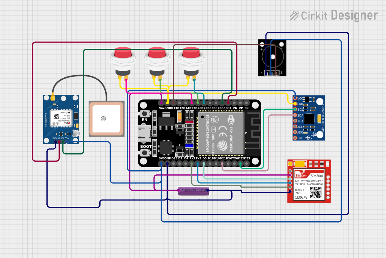
The circuit in question is designed to interface an ESP32 microcontroller with a variety of peripherals including a GPS module (GPS NEO 6M), a motion sensor (MPU-6050), a GSM module (Sim800l), a passive buzzer, and multiple push switches. The circuit is powered by a 3.7V battery. The ESP32 serves as the central processing unit, handling sensor data, GPS communication, GSM communication, and user input from the push switches. The passive buzzer is used for audio feedback. The circuit is likely intended for a tracking device that can communicate its position and sensor data remotely.
Component List
ESP32 (30 pin)
- A 30-pin microcontroller with Wi-Fi and Bluetooth capabilities.
- Pins: EN, VP, VN, D34, D35, D32, D33, D25, D26, D27, D14, D12, D13, GND, Vin, D23, D22, TX0, RX0, D21, D19, D18, D5, TX2, RX2, D4, D2, D15, 3V3
MPU-6050
- A motion tracking device with a 3-axis gyroscope and a 3-axis accelerometer.
- Pins: VCC, GND, SCL, SDA, XDA, XCL, AD0, INT
Sim800l
- A GSM/GPRS module that can make calls, send messages, and connect to the internet.
- Pins: NET, RST, VCC, RXD, TXD, GND
GPS NEO 6M
- A GPS module capable of providing accurate geographical coordinates.
- Pins: VCC, RX, TX, GND
3.7v battery
- A power source for the circuit.
- Pins: +, -
Elegoo Passive Buzzer
- A simple buzzer for audio feedback.
- Pins: GND, VCC, OUTPUT
2Pin Push Switch (x3)
- A simple push-button switch for user input.
- Pins: Input +, Output +
Wiring Details
ESP32 (30 pin)
- D34 connected to GPS NEO 6M TX
- D35 connected to GPS NEO 6M RX
- D25 connected to Push Switch 1 Output +
- D26 connected to Push Switch 2 Output +
- D27 connected to Push Switch 3 Output +
- D13 connected to Passive Buzzer OUTPUT
- GND connected to GND of all components
- Vin connected to 3.7v battery +
- D22 (SCL) connected to MPU-6050 SCL
- D21 (SDA) connected to MPU-6050 SDA
- D5 connected to Sim800l RST
- TX2 connected to Sim800l RXD
- RX2 connected to Sim800l TXD
- 3V3 connected to VCC of GPS NEO 6M, Passive Buzzer, and MPU-6050
MPU-6050
- VCC connected to ESP32 3V3
- GND connected to ESP32 GND
- SCL connected to ESP32 D22
- SDA connected to ESP32 D21
Sim800l
- VCC connected to 3.7v battery +
- RST connected to ESP32 D5
- RXD connected to ESP32 TX2
- TXD connected to ESP32 RX2
- GND connected to ESP32 GND
GPS NEO 6M
- VCC connected to ESP32 3V3
- RX connected to ESP32 D35
- TX connected to ESP32 D34
- GND connected to ESP32 GND
3.7v battery
- connected to ESP32 Vin and Sim800l VCC
- connected to ESP32 GND
Elegoo Passive Buzzer
- VCC connected to ESP32 3V3
- OUTPUT connected to ESP32 D13
- GND connected to ESP32 GND
2Pin Push Switch 1
- Input + connected to ESP32 GND
- Output + connected to ESP32 D25
2Pin Push Switch 2
- Input + connected to ESP32 GND
- Output + connected to ESP32 D26
2Pin Push Switch 3
- Input + connected to ESP32 GND
- Output + connected to ESP32 D27
Documented Code
No code was provided for the microcontrollers in the circuit. The documentation of the code would typically include descriptions of the functionality implemented, setup and loop functions for an Arduino-based microcontroller like the ESP32, and any functions or libraries used to interface with the peripherals. Since no code is available, this section cannot be completed.