
ESP32-CAM and Arduino Nano Radiation Detection System with GPS and Wi-Fi Connectivity
View and Edit Project In Cirkit Designer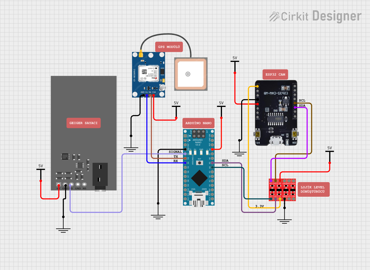
Circuit Documentation
Summary
This circuit integrates an ESP32-CAM module, an Arduino Nano, a GPS NEO 6M module, a Geiger Counter, and a Bi-Directional Logic Level Converter. The ESP32-CAM module is used for capturing images and streaming them over Wi-Fi. The Arduino Nano collects GPS data and radiation levels from the GPS NEO 6M module and the Geiger Counter, respectively. The Bi-Directional Logic Level Converter ensures proper voltage levels between the ESP32-CAM and the Arduino Nano.
Component List
ESP32-CAM MB FLIP
- Description: A camera module with Wi-Fi capabilities.
- Pins: 3.3V, IO16, IO0, GND, VCC, IO3RX, IO1TX, 5V, IO12, IO13, IO15, IO14, IO2, IO4
Arduino Nano
- Description: A small, complete, and breadboard-friendly board based on the ATmega328P.
- Pins: D1/TX, D0/RX, RESET, GND, D2, D3, D4, D5, D6, D7, D8, D9, D10, D11/MOSI, D12/MISO, VIN, 5V, A7, A6, A5, A4, A3, A2, A1, A0, AREF, 3V3, D13/SCK
GPS NEO 6M
- Description: A GPS module for obtaining location data.
- Pins: VCC, RX, TX, GND
Geiger Counter
- Description: A device for measuring ionizing radiation.
- Pins: +5v, GND, SIGNAL
Bi-Directional Logic Level Converter
- Description: A module for converting voltage levels between different components.
- Pins: HV1, HV2, HV, GND, HV3, HV4, LV1, LV2, LV, LV3, LV4
Vcc
- Description: Power supply providing voltage.
- Pins: Vcc
GND
- Description: Ground connection.
- Pins: GND
Wiring Details
ESP32-CAM MB FLIP
- 3.3V connected to LV of Bi-Directional Logic Level Converter
- GND connected to GND of GND
- VCC connected to Vcc of Vcc
- IO15 connected to HV2 of Bi-Directional Logic Level Converter
- IO14 connected to HV1 of Bi-Directional Logic Level Converter
Arduino Nano
- D3 connected to RX of GPS NEO 6M
- D4 connected to TX of GPS NEO 6M
- GND connected to GND of GND
- D2 connected to SIGNAL of Geiger Counter
- 5V connected to Vcc of Vcc
- A5 connected to LV2 of Bi-Directional Logic Level Converter
- A4 connected to LV1 of Bi-Directional Logic Level Converter
GPS NEO 6M
- VCC connected to Vcc of Vcc
- RX connected to D3 of Arduino Nano
- TX connected to D4 of Arduino Nano
- GND connected to GND of GND
Geiger Counter
- +5v connected to Vcc of Vcc
- GND connected to GND of GND
- SIGNAL connected to D2 of Arduino Nano
Bi-Directional Logic Level Converter
- LV connected to 3.3V of ESP32-CAM MB FLIP
- HV2 connected to IO15 of ESP32-CAM MB FLIP
- HV1 connected to IO14 of ESP32-CAM MB FLIP
- LV2 connected to A5 of Arduino Nano
- LV1 connected to A4 of Arduino Nano
- HV connected to Vcc of Vcc
- GND connected to GND of GND
Code Documentation
ESP32-CAM MB FLIP Code
#include <Arduino.h>
#include "esp_camera.h"
#include <WiFi.h>
#include "esp_timer.h"
#include "img_converters.h"
#include "fb_gfx.h"
#include "soc/soc.h"
#include "soc/rtc_cntl_reg.h"
#include "esp_http_server.h"
#include <ArduinoJson.h>
#include <Wire.h>

#define I2C_SLAVE_ADDRESS 8
#define SDA_PIN 14
#define SCL_PIN 15
String receivedData = "";
float latitude = 0.0;
float longitude = 0.0;
float radyoAktifDurum = 0.0f;

// Wi-Fi Ayarları
const char *ssid = "Bilisim";
const char *password = "bilsem80";

void parseJSON(String json)
{
    // Allocate the JSON document
    JsonDocument doc;
    // JSON verisini parse et
    DeserializationError error = deserializeJson(doc, json);

    if (error)
    {
        Serial.print("JSON Ayrıştırma hatası: ");
        Serial.println(error.c_str());
    }
    else
    {
        // JSON verilerinden değerleri çek
        latitude = doc["lat"];
        longitude = doc["lng"];
        radyoAktifDurum = doc["counter"];
    }
}

// Arduino'dan veri al
void receiveEvent(int bytes)
{
    while (Wire.available())
    {
        char c = Wire.read();
        if (c == '{')
        {
            receivedData = "";
            receivedData += c;
        }
        else if (c == '}')
        {
            receivedData += c;
            Serial.println("Gelen JSON: " + receivedData);
            parseJSON(receivedData); // JSON veriyi ayrıştır
        }
        else
        {
            receivedData += c;
        }
    }
}

#define PART_BOUNDARY "123456789000000000000987654321"
#define CAMERA_MODEL_AI_THINKER
#if defined(CAMERA_MODEL_AI_THINKER)
#define PWDN_GPIO_NUM 32
#define RESET_GPIO_NUM -1
#define XCLK_GPIO_NUM 0
#define SIOD_GPIO_NUM 26
#define SIOC_GPIO_NUM 27
#define Y9_GPIO_NUM 35
#define Y8_GPIO_NUM 34
#define Y7_GPIO_NUM 39
#define Y6_GPIO_NUM 36
#define Y5_GPIO_NUM 21
#define Y4_GPIO_NUM 19
#define Y3_GPIO_NUM 18
#define Y2_GPIO_NUM 5
#define VSYNC_GPIO_NUM 25
#define HREF_GPIO_NUM 23
#define PCLK_GPIO_NUM 22
#else
#error "Camera model not selected"
#endif

static const char *_STREAM_CONTENT_TYPE = "multipart/x-mixed-replace;boundary=" PART_BOUNDARY;
static const char *_STREAM_BOUNDARY = "\r\n--" PART_BOUNDARY "\r\n";
static const char *_STREAM_PART = "Content-Type: image/jpeg\r\nContent-Length: %u\r\n\r\n";
httpd_handle_t camera_httpd = NULL;
httpd_handle_t stream_httpd = NULL;

static const char PROGMEM INDEX_HTML[] = R"rawliteral(
<html>
 <head>
   <title>ESP32-CAM Radyasyon Tespit Sistemi</title>
   <meta name="viewport" content="width=device-width, initial-scale=1">
   <style>
     body { font-family: Arial; text-align: center; margin: 0px auto; padding-top: 30px; }
     .button {
       background-color: #2f4468;
       border: none;
       color: white;
       padding: 10px 20px;
       text-align: center;
       text-decoration: none;
       display: inline-block;
       font-size: 18px;
       margin: 6px 3px;
       cursor: pointer;
     }
     img { width: auto; max-width: 100%; height: auto; }
   </style>
 </head>
 <body>
   <h1>ESP32-CAM Radyasyon Tespit Sistemi</h1>
   <p>Enlem: <span id="lat">0</span></p>
   <p>Boylam: <span id="lon">0</span></p>
   <p>Radyo Aktivite: <span id="radyoaktif">0</span></p>
   <img src="" id="photo">
   <script>
     function updateCoordinates() {
       fetch('/gps')
         .then(response => response.json())
         .then(data => {
           document.getElementById('lat').textContent = data.latitude;
           document.getElementById('lon').textContent = data.longitude;
           document.getElementById('radyoaktif').textContent = data.radyoAktifDurum;
         });
     }
     setInterval(updateCoordinates, 2000