
Circuit Documentation
Summary of the Circuit
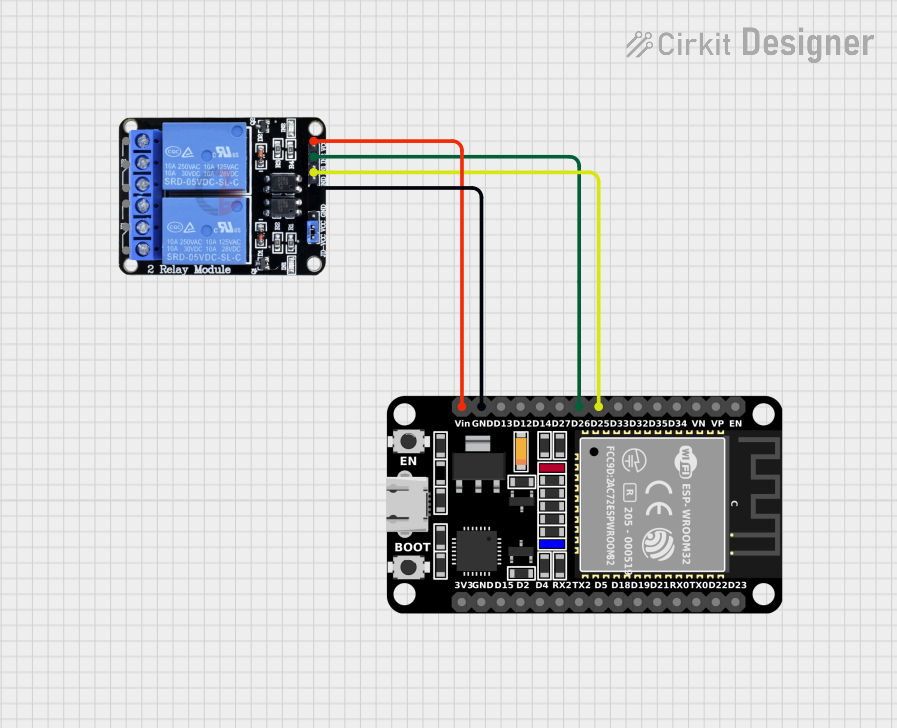
This circuit is designed to control a two-channel relay module using an ESP32 microcontroller. The ESP32 is a versatile microcontroller with Wi-Fi and Bluetooth capabilities, which can be used for a variety of IoT applications. In this circuit, the ESP32 is used to switch the relay channels on and off, potentially to control larger loads that the ESP32 cannot handle directly.
Component List
ESP32 (30 pin)
- Description: A 30-pin microcontroller with Wi-Fi and Bluetooth capabilities.
- Pins: EN, VP, VN, D34, D35, D32, D33, D25, D26, D27, D14, D12, D13, GND, Vin, D23, D22, TX0, RX0, D21, D19, D18, D5, TX2, RX2, D4, D2, D15, 3V3
- Purpose: Acts as the central processing unit of the circuit, controlling the relay module based on programmed logic.
Two Channel Relay 5v
- Description: A relay module with two channels that can be controlled independently.
- Pins: VCC, IN2, IN1, GND, NC2, C2, NO2, NC1, C1, NO1
- Purpose: Allows the ESP32 to control high power devices, isolating the microcontroller from the high power circuit.
Wiring Details
ESP32 (30 pin)
- D25: Connected to IN1 on the Two Channel Relay 5v to control the first relay channel.
- D26: Connected to IN2 on the Two Channel Relay 5v to control the second relay channel.
- GND: Connected to GND on the Two Channel Relay 5v to establish a common ground.
- Vin: Connected to VCC on the Two Channel Relay 5v to provide power to the relay module.
Two Channel Relay 5v
- IN1: Controlled by D25 on the ESP32.
- IN2: Controlled by D26 on the ESP32.
- GND: Connected to GND on the ESP32 to establish a common ground.
- VCC: Powered by Vin from the ESP32.
Documented Code
No code has been provided for the microcontroller. To fully utilize this circuit, embedded code for the ESP32 is required to define the behavior of the relay control. The code should initialize the GPIO pins connected to IN1 and IN2 as outputs and then set them high or low to activate or deactivate the relays, respectively.