Cirkit Designer
Your all-in-one circuit design IDE
Home /
Project Documentation
Arduino Nano-Based GPS Tracker with GSM Communication and IR Obstacle Detection
Circuit Documentation
Summary
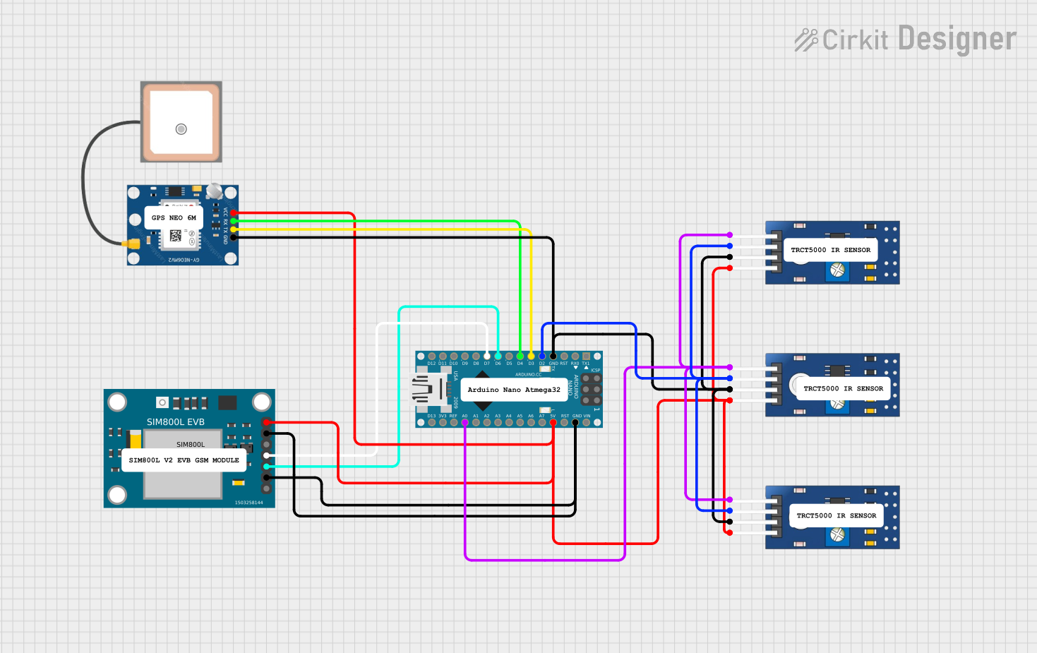
This circuit integrates an Arduino Nano microcontroller with a SIM800L EVB GSM module, a GPS NEO 6M module, and multiple TCRT 5000 IR sensors. The Arduino Nano serves as the central processing unit, interfacing with the GSM module for cellular communication, the GPS module for location tracking, and the IR sensors for detecting proximity or measuring the intensity of infrared light.
Component List
Arduino Nano
- Microcontroller board based on the ATmega328P
- Offers a variety of digital and analog I/O pins
- Can be powered via USB or an external power supply
SIM800L EVB GSM Module
- GSM/GPRS module for cellular communication
- Supports quad-band 850/900/1800/1900MHz
- Can be used for SMS, data, and voice applications
GPS NEO 6M Module
- GPS module for satellite-based location tracking
- Utilizes the NEO 6M GPS chipset
- Provides location coordinates, time, and other data
TCRT 5000 IR Sensor
- Infrared reflective sensor
- Includes both an infrared emitter and phototransistor
- Can be used for line tracking or obstacle detection
Wiring Details
Arduino Nano
- GND: Connected to the ground pins of the GPS NEO 6M, SIM800L EVB GSM, and all TCRT 5000 IR sensors.
- D2: Connected to the digital output (DO) pins of all TCRT 5000 IR sensors.
- D3: Connected to the TX pin of the GPS NEO 6M.
- D4: Connected to the RX pin of the GPS NEO 6M.
- D6: Connected to the TXD pin of the SIM800L EVB GSM.
- D7: Connected to the RXD pin of the SIM800L EVB GSM.
- 5V: Powers the SIM800L EVB GSM, GPS NEO 6M, and all TCRT 5000 IR sensors.
- A0: Connected to the analog output (AO) pins of all TCRT 5000 IR sensors.
SIM800L EVB GSM Module
- GND: Connected to the GND pin of the Arduino Nano.
- TXD: Connected to D6 on the Arduino Nano.
- RXD: Connected to D7 on the Arduino Nano.
- VCC: Powered by the 5V output from the Arduino Nano.
GPS NEO 6M Module
- GND: Connected to the GND pin of the Arduino Nano.
- TX: Connected to D3 on the Arduino Nano.
- RX: Connected to D4 on the Arduino Nano.
- VCC: Powered by the 5V output from the Arduino Nano.
TCRT 5000 IR Sensor
- GND: Connected to the GND pin of the Arduino Nano.
- DO: Connected to D2 on the Arduino Nano.
- AO: Connected to A0 on the Arduino Nano.
- VCC: Powered by the 5V output from the Arduino Nano.
Documented Code
Arduino Nano Code (sketch.ino)
void setup() {
  // put your setup code here, to run once:

}

void loop() {
  // put your main code here, to run repeatedly:

}
Additional Notes
- The code provided for the Arduino Nano is a template with empty
setup()andloop()functions. The actual implementation should include initialization of the serial interfaces, configuration of the I/O pins, and the main logic for interacting with the GSM, GPS, and IR sensor modules. - The
documentation.txtfile is empty and does not contain any additional information.