Simple LED Circuit with Resistor
Circuit Documentation
Summary of the Circuit
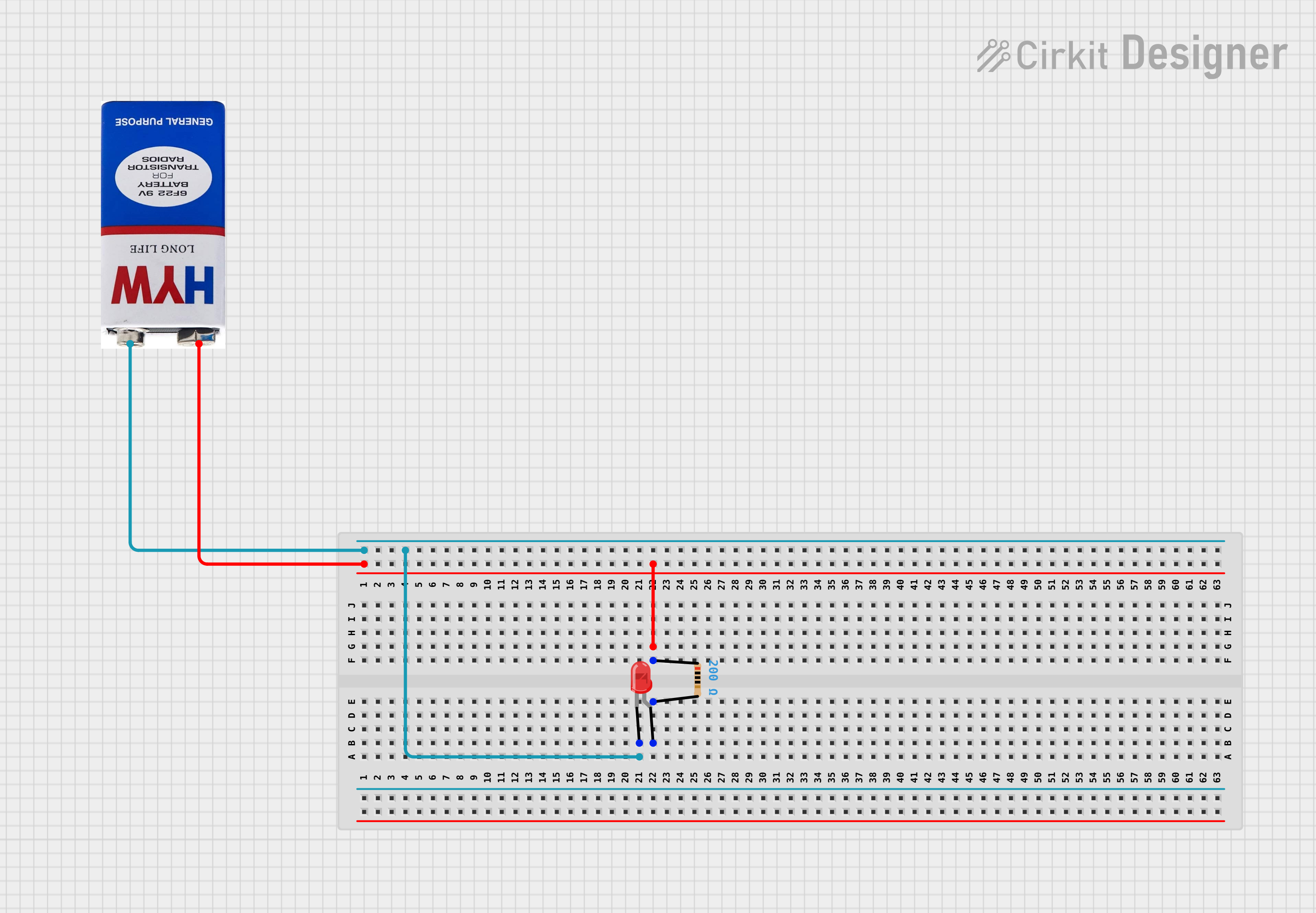
The circuit described by the provided inputs is a simple LED circuit powered by a 9V battery. The circuit includes a single LED, a resistor, and a battery as its power source. The LED has two pins, an anode and a cathode, with the anode being the longer lead and typically connected to the positive side of the power source. The cathode is connected to the negative side of the power source, often through a current-limiting resistor to prevent damage to the LED. In this circuit, the resistor is used to limit the current flowing through the LED, ensuring that it operates within safe parameters.
Component List
9V Battery
- Description: A standard 9V battery used as the power source for the circuit.
- Pins:
+(positive),-(negative) - Purpose: To provide the necessary voltage and current to power the LED.
LED: Two Pin (red)
- Description: A red-colored LED with two pins, anode and cathode.
- Pins:
anode,cathode - Purpose: To emit light when powered, serving as the visual indicator or output device in the circuit.
Resistor
- Description: A passive two-terminal electrical component that implements electrical resistance as a circuit element.
- Pins:
pin1,pin2 - Properties: Resistance value of 200 Ohms.
- Purpose: To limit the current flowing through the LED, protecting it from excessive current that could cause damage.
Wiring Details
9V Battery
- Positive Pin (
+): Connected topin1of the Resistor. - Negative Pin (
-): Connected to thecathodeof the LED.
LED: Two Pin (red)
- Anode: Connected to
pin2of the Resistor. - Cathode: Connected to the
-(negative) pin of the 9V Battery.
Resistor
- Pin1: Connected to the
+(positive) pin of the 9V Battery. - Pin2: Connected to the
anodeof the LED.
Documented Code
There is no microcontroller or embedded code associated with this circuit as per the provided inputs. Therefore, this section is not applicable to the current documentation.
This documentation provides a comprehensive overview of the circuit, including the purpose and connection details of each component. If a microcontroller or additional components are introduced to the circuit in the future, the documentation will be updated accordingly to include the necessary details and embedded code.