
Circuit Documentation
Summary of the Circuit
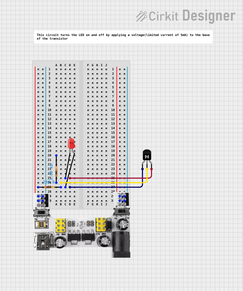
This circuit appears to be a simple LED driver using an NPN transistor as a switch. The LED is connected to the collector of the transistor, and a resistor is connected to the base to limit the current. The emitter of the transistor is connected to the ground. The circuit is powered by a breadboard power module that can provide either 3.3V or 5V. There is no microcontroller code provided, indicating that the circuit is likely to be manually switched or always on, depending on the base drive.
Component List
Breadboard Power Module (3.3/5V)
- Description: A module that provides selectable 3.3V or 5V power supply to the breadboard.
- Pins: +, -, VCC (5V), GND, VCC (3.3V)
Resistor (200 Ohms)
- Description: A resistor with a resistance of 200 Ohms.
- Pins: pin1, pin2
LED: Two Pin (red)
- Description: A red LED with two pins: anode and cathode.
- Pins: cathode, anode
NPN Transistor (EBC)
- Description: A standard NPN bipolar junction transistor with emitter, base, and collector pins.
- Pins: emitter, base, collector
Resistor (1000 Ohms)
- Description: A resistor with a resistance of 1000 Ohms.
- Pins: pin1, pin2
Comment
- Description: A placeholder for comments, not an actual electronic component.
Wiring Details
Breadboard Power Module (3.3/5V)
- +: Connected to the anode of the LED through a 200 Ohm resistor.
- -: Connected to the emitter of the NPN transistor.
Resistor (200 Ohms)
- pin1: Connected to the + of the Breadboard Power Module.
- pin2: Connected to the anode of the LED.
LED: Two Pin (red)
- anode: Connected to pin2 of the 200 Ohm resistor.
- cathode: Connected to the collector of the NPN transistor.
NPN Transistor (EBC)
- emitter: Connected to the - of the Breadboard Power Module.
- base: Connected to pin1 of the 1000 Ohm resistor.
- collector: Connected to the cathode of the LED.
Resistor (1000 Ohms)
- pin1: Connected to the base of the NPN transistor.
- pin2: This connection is not specified in the net list and may be assumed to be floating or connected to a control signal not documented.
Documented Code
No code has been provided for this circuit. If the circuit is intended to be controlled by a microcontroller or other programmable device, the code would be necessary to document the control behavior. Since no code is present, this section is not applicable for the current documentation.