
Arduino Mega 2560-Based Digital Counter with Pushbuttons and Seven Segment Displays
View and Edit Project In Cirkit Designer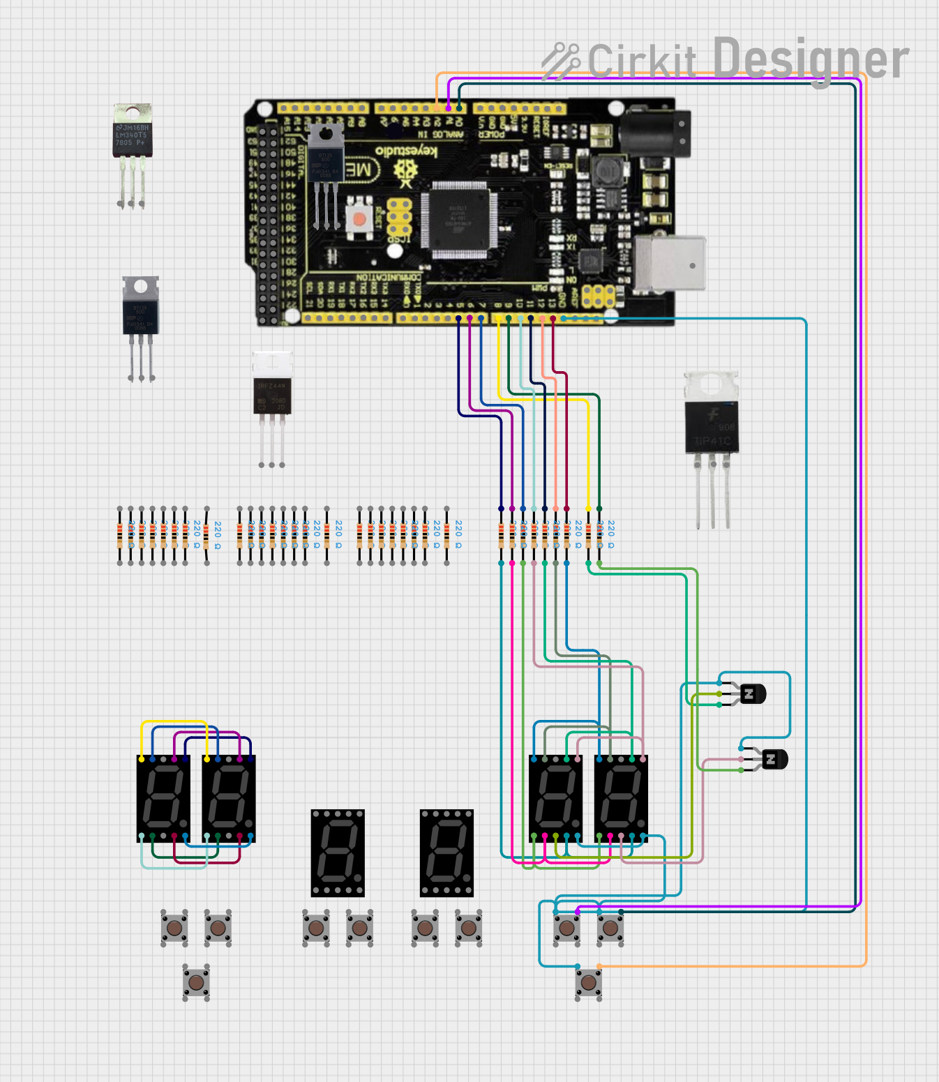
Circuit Documentation
Summary
This circuit is designed to interface with a Mega 2560 R3 microcontroller to control a seven-segment display using multiple pushbuttons. The pushbuttons are used to increment, decrement, and reset the displayed number. The circuit also includes resistors to limit current and transistors to drive the seven-segment displays.
Component List
Pushbutton
- Description: A simple pushbutton switch.
- Pins: Pin 1 (in), Pin 2 (in), Pin 3 (out), Pin 4 (out)
Seven Segment Display (Wokwi Compatible)
- Description: A seven-segment display compatible with Wokwi.
- Pins: G, F, COM.2, B, A, E, D, COM.1, C, DP
Resistor
- Description: A resistor with a resistance of 220 Ohms.
- Pins: pin1, pin2
NPN Transistor (ECB)
- Description: A standard NPN transistor.
- Pins: emitter, collector, base
Mega 2560 R3
- Description: A microcontroller board based on the ATmega2560.
- Pins: ICSP port GND, ICSP port Reset, ICSP port MOSI, ICSP port SCK, ICSP port +VCC, ICSP port MISO, SCL, SDA, AREF, GND, D13 (PWM), D12 (PWM), D11 (PWM), D10 (PWM), D9 (PWM), D8 (PWM), D7 (PWM), D6 (PWM), D5 (PWM), D4 (PWM), D3 (PWM), D2 (PWM), D1 (TX0), D0 (RX0), D14 (TX3), D15 (RX3), D16 (TX2), D17 (RX2), D18 (TX1), D19 (RX1), D20 (SDA), D21 (SCL), + 5VCC, D22, D23, D24, D25, D26, D27, D28, D29, D30, D31, D32, D33, D34, D35, D36, D37, D38, D39, D40, D41, D42, D43, D44, D45, D46, D47, D48, D49, D50, D51, D52, D53, NC, IOREF, Reset, +3V3, +VCC IN, A0, A1, A2, A3, A4, A5, A6, A7, A8, A9, A10, A11, A12, A13, A14, A15, USB port
Wiring Details
Pushbutton
Pin 1 (in) is connected to:
- Seven Segment Display (Wokwi Compatible): DP
- NPN Transistor (ECB): emitter
- Mega 2560 R3: GND
Pin 3 (out) is connected to:
- Mega 2560 R3: A0
Pushbutton
Pin 1 (in) is connected to:
- Seven Segment Display (Wokwi Compatible): DP
- NPN Transistor (ECB): emitter
- Mega 2560 R3: GND
Pin 3 (out) is connected to:
- Mega 2560 R3: A1
Pushbutton
Pin 1 (in) is connected to:
- Seven Segment Display (Wokwi Compatible): DP
- NPN Transistor (ECB): emitter
- Mega 2560 R3: GND
Pin 3 (out) is connected to:
- Mega 2560 R3: A2
Resistor
pin1 is connected to:
- Mega 2560 R3: D13 (PWM)
pin2 is connected to:
- Seven Segment Display (Wokwi Compatible): G
Resistor
pin1 is connected to:
- Mega 2560 R3: D12 (PWM)
pin2 is connected to:
- Seven Segment Display (Wokwi Compatible): F
Resistor
pin1 is connected to:
- Mega 2560 R3: D11 (PWM)
pin2 is connected to:
- Seven Segment Display (Wokwi Compatible): A
Resistor
pin1 is connected to:
- Mega 2560 R3: D10 (PWM)
pin2 is connected to:
- Seven Segment Display (Wokwi Compatible): B
Resistor
pin1 is connected to:
- Mega 2560 R3: D9 (PWM)
pin2 is connected to:
- Seven Segment Display (Wokwi Compatible): C
Resistor
pin1 is connected to:
- Mega 2560 R3: D8 (PWM)
pin2 is connected to:
- Seven Segment Display (Wokwi Compatible): D
Resistor
pin1 is connected to:
- Mega 2560 R3: D7 (PWM)
pin2 is connected to:
- Seven Segment Display (Wokwi Compatible): E
Resistor
pin1 is connected to:
- Mega 2560 R3: D6 (PWM)
pin2 is connected to:
- Seven Segment Display (Wokwi Compatible): G
Resistor
pin1 is connected to:
- Mega 2560 R3: D5 (PWM)
pin2 is connected to:
- Seven Segment Display (Wokwi Compatible): F
NPN Transistor (ECB)
emitter is connected to:
- Pushbutton: Pin 1 (in)
- Mega 2560 R3: GND
collector is connected to:
- Seven Segment Display (Wokwi Compatible): COM.1
base is connected to:
- Resistor: pin2
Mega 2560 R3
GND is connected to:
- Pushbutton: Pin 1 (in)
- NPN Transistor (ECB): emitter
D13 (PWM) is connected to:
- Resistor: pin1
D12 (PWM) is connected to:
- Resistor: pin1
D11 (PWM) is connected to:
- Resistor: pin1
D10 (PWM) is connected to:
- Resistor: pin1
D9 (PWM) is connected to:
- Resistor: pin1
D8 (PWM) is connected to:
- Resistor: pin1
D7 (PWM) is connected to:
- Resistor: pin1
D6 (PWM) is connected to:
- Resistor: pin1
D5 (PWM) is connected to:
- Resistor: pin1
A0 is connected to:
- Pushbutton: Pin 3 (out)
A1 is connected to:
- Pushbutton: Pin 3 (out)
A2 is connected to:
- Pushbutton: Pin 3 (out)
Code Documentation
//Tanımlamalar
const int d1A =12;
const int d1B =13;
const int d1C =5;
const int d1D =6;
const int d1E =7;
const int d1F =11;
const int d1G =10;

const int onlar1Bas =8;
const int birler1Bas =9;

const int btn1Up =A0;
const int btn1Down =A1;
const int reset1Buton =A2;

int numberValue =0;
char statusBtnUp = '1';
char statusBtnDown = '1';
char statusBtnReset ='1';

void setup() {
  showNumber (numberValue);
  pinMode (d1A, OUTPUT);
  pinMode (d1B, OUTPUT);
  pinMode (d1C, OUTPUT);
  pinMode (d1D, OUTPUT);
  pinMode (d1E, OUTPUT);
  pinMode (d1F, OUTPUT);
  pinMode (d1G, OUTPUT);

  pinMode (onlar1Bas, OUTPUT);
  pinMode (birler1Bas, OUTPUT);

  pinMode (btn1Up, INPUT_PULL