Arduino UNO Based Flame Detection System with Alert Indicators
Circuit Documentation
Summary of the Circuit
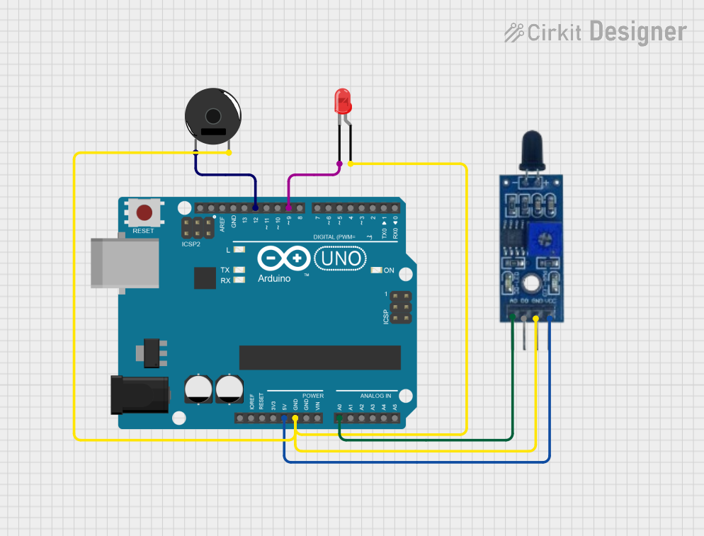
The circuit described in the provided inputs consists of an Arduino UNO microcontroller interfaced with a flame sensor, a piezo buzzer, and a red two-pin LED. The flame sensor is used to detect the presence of a flame, and upon detection, the Arduino activates the LED and the piezo buzzer as indicators. The Arduino UNO reads the analog value from the flame sensor and controls the LED and buzzer based on the sensor's output.
Component List
Arduino UNO
- Description: A microcontroller board based on the ATmega328P.
- Purpose: Acts as the central processing unit of the circuit, reading sensor data and controlling the LED and buzzer.
- Pins: UNUSED, IOREF, Reset, 3.3V, 5V, GND, Vin, A0-A5, SCL, SDA, AREF, D0-D13.
Piezo Buzzer
- Description: An electronic device that emits sound when an electric current is applied.
- Purpose: Serves as an audible alert when a flame is detected.
- Pins: pin 1, pin 2.
LED: Two Pin (red)
- Description: A red light-emitting diode with an anode and cathode.
- Purpose: Provides a visual indication when a flame is detected.
- Pins: cathode, anode.
Flame Sensor
- Description: A sensor that detects the presence of a flame or fire.
- Purpose: Senses the flame and provides an analog signal to the Arduino.
- Pins: VCC, GND, D0, A0.
Wiring Details
Arduino UNO
- 5V connected to Flame Sensor VCC.
- GND connected to LED anode, Flame Sensor GND, and Piezo Buzzer pin 2.
- A0 connected to Flame Sensor A0.
- D12 connected to Piezo Buzzer pin 1.
- D9 connected to LED cathode.
Piezo Buzzer
- pin 1 connected to Arduino UNO D12.
- pin 2 connected to Arduino UNO GND.
LED: Two Pin (red)
- cathode connected to Arduino UNO D9.
- anode connected to Arduino UNO GND.
Flame Sensor
- VCC connected to Arduino UNO 5V.
- GND connected to Arduino UNO GND.
- A0 connected to Arduino UNO A0.
Documented Code
#include<SoftwareSerial.h>

int sensorPin = A0; // select the input pin for the LDR

int sensorValue = 0; // variable to store the value coming from the sensor

int led = 9; // Output pin for LED

int buzzer = 12; // Output pin for Buzzer

void setup() {
  // declare the ledPin and buzzer as an OUTPUT:
  pinMode(led, OUTPUT);
  pinMode(buzzer, OUTPUT);
  Serial.begin(9600);
}

void loop() {
  Serial.println("Welcome to TechPonder Flame Sensor Tutorial");
  sensorValue = analogRead(sensorPin);
  Serial.println(sensorValue);

  if (sensorValue < 100) {
    Serial.println("Fire Detected");
    Serial.println("LED on");
    digitalWrite(led, HIGH);
    digitalWrite(buzzer, HIGH);
    delay(1000);
  }

  digitalWrite(led, LOW);
  digitalWrite(buzzer, LOW);
  delay(sensorValue);
}
Filename: sketch.ino
Description: This code initializes the Arduino UNO to read the analog value from the flame sensor connected to pin A0. If the sensor value is below 100, indicating the presence of a flame, the Arduino sets the LED (connected to pin D9) and the buzzer (connected to pin D12) to HIGH, turning them on. After a delay, both the LED and buzzer are turned off, and the cycle repeats with a delay based on the sensor value.