
Arduino UNO Based IR and LDR Sensor Array with LED Indicators
View and Edit Project In Cirkit Designer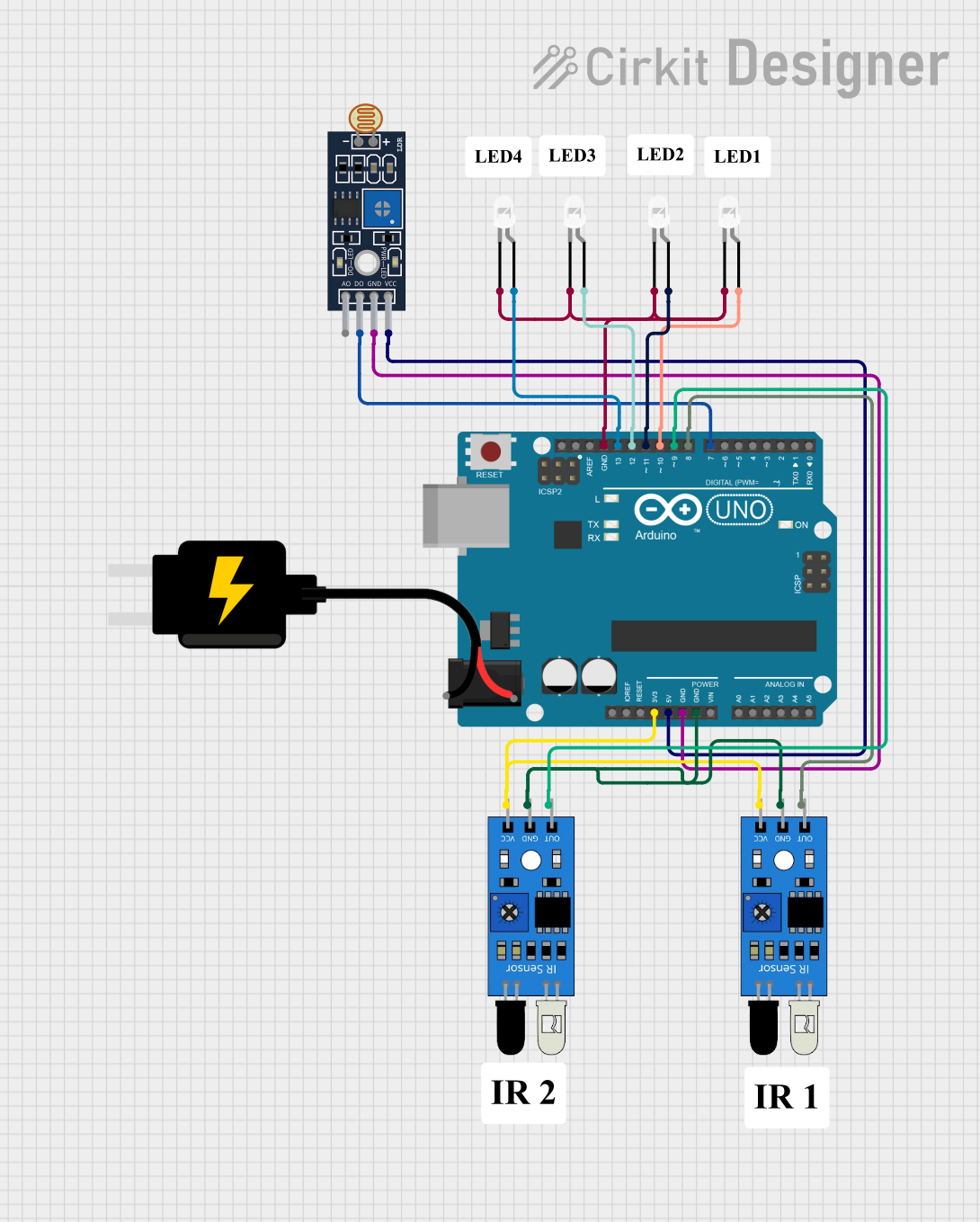
Circuit Documentation
Summary of the Circuit
This circuit is designed to interface an Arduino UNO with multiple sensors and LEDs. The sensors include two IR sensors and one LDR sensor module (LM393). The circuit also includes four white LEDs that are controlled by the Arduino UNO. The IR sensors are powered by the 3.3V output from the Arduino, while the LDR sensor module is powered by the 5V output. The LEDs are connected to digital pins on the Arduino and share a common ground. The purpose of the circuit is not specified, but it could be used for light detection and infrared object detection, with visual indicators provided by the LEDs.
Component List
Arduino UNO
- Microcontroller board based on the ATmega328P
- Provides digital and analog I/O pins
- Can be powered via USB or an external power supply
IR Sensor (x2)
- Infrared sensor for object detection
- Includes an output pin to interface with a microcontroller
- Requires a power supply and a ground connection
Sensor LDR LM393
- Light-dependent resistor sensor module
- Outputs a digital signal based on light intensity
- Requires a power supply and a ground connection
LED: Two Pin (White) (x4)
- Standard white LEDs with an anode and cathode
- Used as visual indicators in the circuit
DC Source 5V
- Provides a 5V power supply to the circuit
- Has VCC and GND pins for power distribution
Wiring Details
Arduino UNO
- 3.3V pin provides power to both IR sensors
- 5V pin provides power to the LDR sensor module
- GND pin is connected to the ground pins of all sensors and the cathodes of all LEDs
- Digital pins D13, D12, D11, and D10 are connected to the anodes of the four LEDs
- Digital pins D9 and D8 are connected to the output pins of the IR sensors
- Digital pin D7 is connected to the digital output pin of the LDR sensor module
IR Sensor
- VCC pin connected to 3.3V on Arduino UNO
- GND pin connected to GND on Arduino UNO
- OUT pin connected to digital pins D9 and D8 on Arduino UNO (for each sensor)
Sensor LDR LM393
- VCC pin connected to 5V on Arduino UNO
- GND pin connected to GND on Arduino UNO
- D0 pin connected to digital pin D7 on Arduino UNO
LED: Two Pin (White)
- Cathode pin connected to GND on Arduino UNO
- Anode pin connected to digital pins D13, D12, D11, and D10 on Arduino UNO (one LED per pin)
Documented Code
Arduino UNO Code (sketch.ino)
void setup() {
  // put your setup code here, to run once:

}

void loop() {
  // put your main code here, to run repeatedly:

}
Note: The provided code is a template and does not include specific functionality. It needs to be completed with the logic to control the LEDs based on the sensor inputs.