
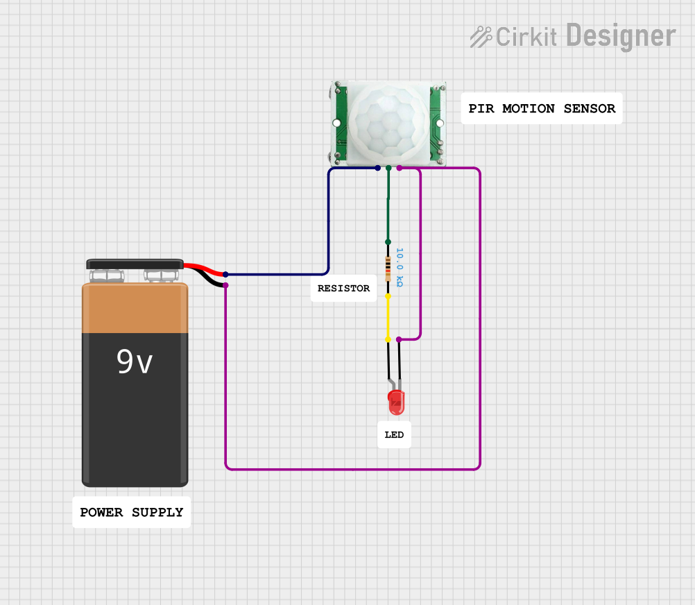
Circuit Documentation
Summary
This document provides a detailed description of a simple motion-activated LED circuit. The circuit uses a PIR (Passive Infrared) motion sensor to detect motion and subsequently light up an LED. The circuit is powered by a 9V battery and includes a resistor to limit the current flowing through the LED.
Component List
PIR/Motion Sensor
- Pins: GND, OUTPUT, VCC
- Description: A sensor that detects motion by measuring infrared light radiating from objects in its field of view.
- Purpose in Circuit: Detects motion and sends a signal to activate the LED.
9V Battery
- Pins: -, +
- Description: A power source providing 9 volts of DC power.
- Purpose in Circuit: Supplies power to the entire circuit.
LED: Two Pin (red)
- Pins: cathode, anode
- Description: A light-emitting diode that emits red light when current flows through it.
- Purpose in Circuit: Lights up when motion is detected.
Resistor
- Pins: pin1, pin2
- Description: A 10k Ohm resistor.
- Purpose in Circuit: Limits the current flowing through the LED to prevent damage.
Wiring Details
PIR/Motion Sensor
- GND is connected to the cathode of the LED and the negative terminal of the 9V battery.
- OUTPUT is connected to pin1 of the resistor.
- VCC is connected to the positive terminal of the 9V battery.
9V Battery
- - is connected to the GND pin of the PIR sensor and the cathode of the LED.
- + is connected to the VCC pin of the PIR sensor.
LED: Two Pin (red)
- cathode is connected to the GND pin of the PIR sensor and the negative terminal of the 9V battery.
- anode is connected to pin2 of the resistor.
Resistor
- pin1 is connected to the OUTPUT pin of the PIR sensor.
- pin2 is connected to the anode of the LED.
Code
There is no microcontroller code associated with this circuit.
This document provides a comprehensive overview of the components and wiring details for a motion-activated LED circuit. The PIR sensor detects motion and activates the LED, with a resistor in place to limit the current and protect the LED. The circuit is powered by a 9V battery.