
ESP32-Based Battery-Powered Voltage and Current Monitoring System
View and Edit Project In Cirkit Designer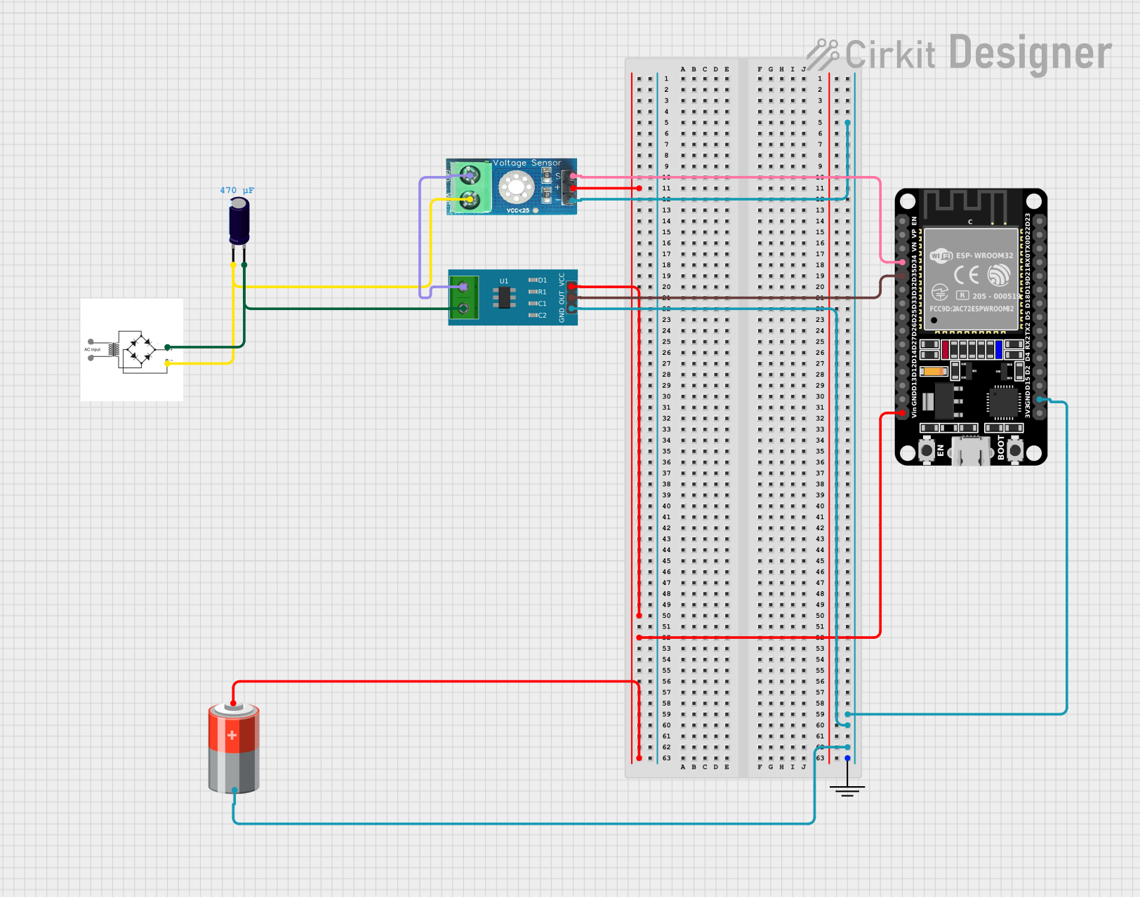
Circuit Documentation
Summary
This circuit involves an ESP32 microcontroller interfacing with a voltage sensor, a current sensor, a bridge rectifier, an electrolytic capacitor, and a 5V battery. The ESP32 reads voltage and current values from the sensors and outputs the data via serial communication.
Component List
GND
- Description: Ground connection
- Pins: GND
Electrolytic Capacitor
- Description: A capacitor used for filtering and energy storage
- Pins: -, +
- Properties:
- Capacitance: 0.00047 Farads
ESP32 (30 pin)
- Description: A microcontroller with Wi-Fi and Bluetooth capabilities
- Pins: EN, VP, VN, D34, D35, D32, D33, D25, D26, D27, D14, D12, D13, GND, Vin, D23, D22, TX0, RX0, D21, D19, D18, D5, TX2, RX2, D4, D2, D15, 3V3
Bridge Rectifier
- Description: Converts AC to DC
- Pins: AC input +, AC input -, +, -
Voltage Sensor DC 25V
- Description: Measures DC voltage up to 25V
- Pins: +, -, output, gnd, vcc
Current Sensor 5A
- Description: Measures current up to 5A
- Pins: 1, 2, GND, OUT, VCC
5V Battery
- Description: Provides 5V power supply
- Pins: +, -
Wiring Details
ESP32 (30 pin)
- D34 is connected to Voltage Sensor DC 25V output
- D35 is connected to Current Sensor 5A OUT
- Vin is connected to:
- Voltage Sensor DC 25V +
- Current Sensor 5A VCC
- 5V Battery +
- GND is connected to:
- GND GND
- Voltage Sensor DC 25V -
- Current Sensor 5A GND
- 5V Battery -
Voltage Sensor DC 25V
- output is connected to ESP32 (30 pin) D34
- + is connected to ESP32 (30 pin) Vin
- - is connected to ESP32 (30 pin) GND
- vcc is connected to:
- Electrolytic Capacitor -
- Bridge Rectifier -
- gnd is connected to Current Sensor 5A 1
Current Sensor 5A
- OUT is connected to ESP32 (30 pin) D35
- VCC is connected to ESP32 (30 pin) Vin
- GND is connected to ESP32 (30 pin) GND
- 2 is connected to:
- Electrolytic Capacitor +
- Bridge Rectifier +
- 1 is connected to Voltage Sensor DC 25V gnd
Electrolytic Capacitor
- + is connected to:
- Current Sensor 5A 2
- Bridge Rectifier +
- - is connected to:
- Voltage Sensor DC 25V vcc
- Bridge Rectifier -
Bridge Rectifier
- + is connected to:
- Electrolytic Capacitor +
- Current Sensor 5A 2
- - is connected to:
- Electrolytic Capacitor -
- Voltage Sensor DC 25V vcc
5V Battery
- + is connected to ESP32 (30 pin) Vin
- - is connected to ESP32 (30 pin) GND
Code Documentation
ESP32 Code
int voltagePin = 34;
int currentPin = 35;

void setup() {
  Serial.begin(115200);
  pinMode(voltagePin, INPUT);
  pinMode(currentPin, INPUT);
}

void loop() {
  float voltage = analogRead(voltagePin) * (3.3/4095.0);
  float current = analogRead(currentPin) * (3.3/4095.0);
  Serial.print("Voltage: "); Serial.println(voltage);
  Serial.print("Current: "); Serial.println(current);
  delay(500);
}
This code initializes the ESP32 to read analog values from the voltage and current sensors connected to pins 34 and 35, respectively. The values are then converted to voltage and current readings and printed to the serial monitor every 500 milliseconds.