
Circuit Documentation
Summary
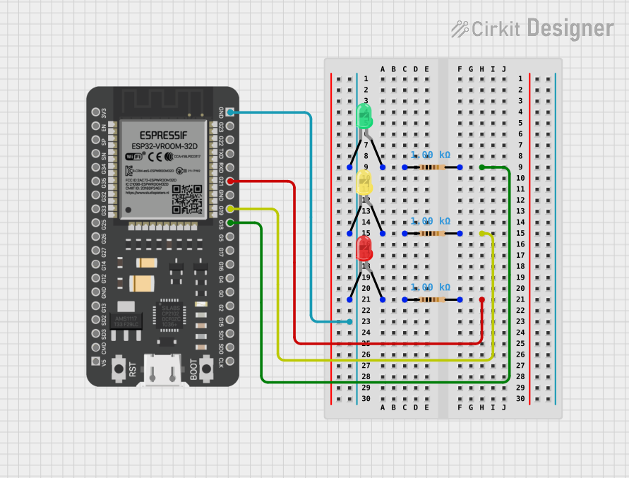
The circuit in question appears to be a simple LED driving circuit controlled by an ESP32 microcontroller. There are three LEDs of different colors (red, yellow, and green), each with a corresponding current-limiting resistor. The ESP32 microcontroller is likely used to control the state (on/off) of each LED, although the provided code is currently empty and does not implement any control logic.
Component List
Resistors
- Resistor 1
- Resistance: 1000 Ohms
- Purpose: To limit the current flowing through the red LED.
- Resistor 2
- Resistance: 1000 Ohms
- Purpose: To limit the current flowing through the yellow LED.
- Resistor 3
- Resistance: 1000 Ohms
- Purpose: To limit the current flowing through the green LED.
LEDs
- LED 1 (Red)
- Type: Two-pin LED
- Color: Red
- Purpose: To emit red light when powered.
- LED 2 (Yellow)
- Type: Two-pin LED
- Color: Yellow
- Purpose: To emit yellow light when powered.
- LED 3 (Green)
- Type: Two-pin LED
- Color: Green
- Purpose: To emit green light when powered.
Microcontroller
- ESP32
- Type: 38-pin ESP32 microcontroller
- Purpose: To control the LEDs.
Wiring Details
Resistors
- Resistor 1
- Connected to: Red LED anode and ESP32 pin G21.
- Resistor 2
- Connected to: Yellow LED anode and ESP32 pin G19.
- Resistor 3
- Connected to: Green LED anode and ESP32 pin G18.
LEDs
- LED 1 (Red)
- Anode: Connected to Resistor 1.
- Cathode: Connected to ESP32 GND.
- LED 2 (Yellow)
- Anode: Connected to Resistor 2.
- Cathode: Connected to ESP32 GND.
- LED 3 (Green)
- Anode: Connected to Resistor 3.
- Cathode: Connected to ESP32 GND.
Microcontroller
- ESP32
- GND: Connected to all LED cathodes.
- G18: Connected to Resistor 3.
- G19: Connected to Resistor 2.
- G21: Connected to Resistor 1.
- Other Pins: Not connected in the current configuration.
Documented Code
ESP32 Microcontroller Code (sketch.ino)
void setup() {
  // put your setup code here, to run once:

}

void loop() {
  // put your main code here, to run repeatedly:

}
Note: The provided code is a template and does not include any functionality to control the LEDs. To control the LEDs, the GPIO pins connected to the resistors (G18, G19, G21) should be configured as outputs and set to HIGH or LOW to turn the corresponding LED on or off.
Additional Notes
- The code for the ESP32 is currently a blank template and needs to be filled in with logic to control the LEDs.
- There is an additional empty text file named "documentation.txt" associated with the microcontroller, which may be intended for further notes or manual documentation.