Cirkit Designer
Your all-in-one circuit design IDE
Home /
Project Documentation
ESP32-Controlled RFID Access System with Keypad and LCD Feedback
Circuit Documentation
Summary
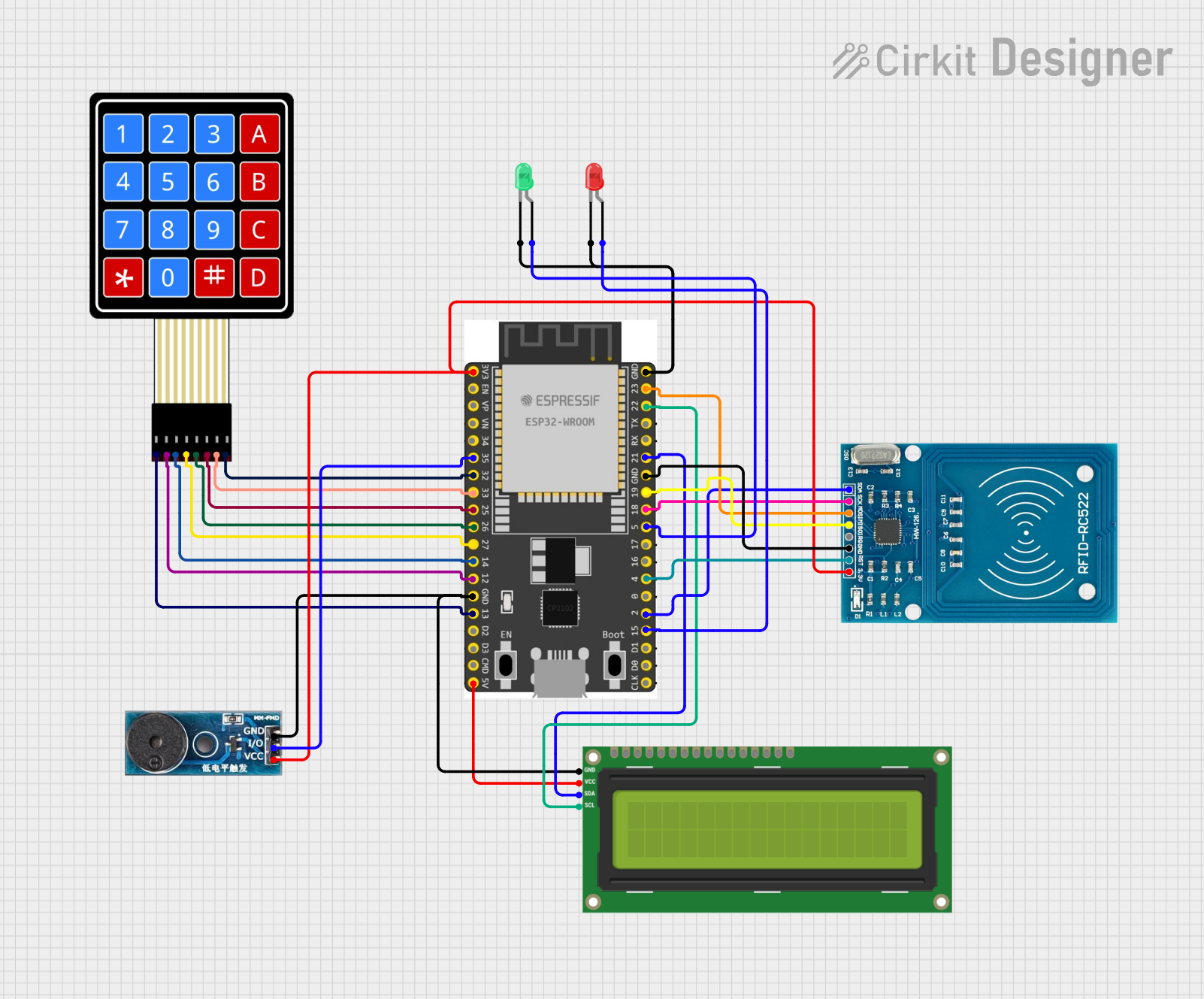
This document provides a detailed overview of a circuit designed to interface an ESP32 Wroom Dev Kit with various peripherals including an RFID-RC522 module, a 4x4 Membrane Matrix Keypad, an I2C LCD 16x2 Screen, two LEDs (red and green), and a Buzzer Module. The ESP32 serves as the central microcontroller unit, managing input from the keypad, communication with the RFID module, output to the LCD screen, and controlling the LEDs and buzzer based on the logic defined in the embedded code.
Component List
RFID-RC522
- Description: A radio frequency identification (RFID) reader module for reading RFID tags.
- Pins: VCC (3.3V), RST, GND, IRQ, MISO, MOSI, SCK, SDA
4X4 Membrane Matrix Keypad
- Description: A 16-button keypad providing user input capabilities.
- Pins: R1, R2, R3, R4, C1, C2, C3, C4
ESP 32 Wroom Dev Kit
- Description: A powerful microcontroller with Wi-Fi and Bluetooth capabilities.
- Pins: 3V3, EN, VP, VN, GPIO 34, GPIO 35, GPIO 32, GPIO 33, GPIO 25, GPIO 26, GPIO 27, GPIO 14, GND, GPIO 13, SD2, SD3, CMD, V5, GPIO 23, GPIO 22, TXD, RXD, GPIO 21, GPIO 19, GPIO 18, GPIO 5, GPIO 17, GPIO 16, GPIO 4, GPIO 0, GPIO 2, GPIO 15, SD1, SD0, CLK
I2C LCD 16x2 Screen
- Description: A liquid crystal display capable of displaying two lines of 16 characters each.
- Pins: SCL, SDA, VCC (5V), GND, VDD, VO, RS, RW, E, D0, D1, D2, D3, D4, D5, D6, D7, BLA, BLK
LED: Two Pin (red)
- Description: A red light-emitting diode for indicating statuses.
- Pins: cathode, anode
LED: Two Pin (green)
- Description: A green light-emitting diode for indicating statuses.
- Pins: cathode, anode
Buzzer Module
- Description: An audible signaling device.
- Pins: GND, Vcc, I/O
Wiring Details
RFID-RC522
- VCC (3.3V) connected to ESP 32 Wroom Dev Kit 3V3
- RST connected to ESP 32 Wroom Dev Kit GPIO 4
- GND connected to ESP 32 Wroom Dev Kit GND
- IRQ not connected
- MISO connected to ESP 32 Wroom Dev Kit GPIO 19
- MOSI connected to ESP 32 Wroom Dev Kit GPIO 23
- SCK connected to ESP 32 Wroom Dev Kit GPIO 18
- SDA connected to ESP 32 Wroom Dev Kit GPIO 2
4X4 Membrane Matrix Keypad
- R1 connected to ESP 32 Wroom Dev Kit GPIO 13
- R2 connected to ESP 32 Wroom Dev Kit GPIO 14
- R3 connected to ESP 32 Wroom Dev Kit GPIO 14
- R4 connected to ESP 32 Wroom Dev Kit GPIO 27
- C1 connected to ESP 32 Wroom Dev Kit GPIO 26
- C2 connected to ESP 32 Wroom Dev Kit GPIO 25
- C3 connected to ESP 32 Wroom Dev Kit GPIO 33
- C4 connected to ESP 32 Wroom Dev Kit GPIO 32
I2C LCD 16x2 Screen
- SCL connected to ESP 32 Wroom Dev Kit GPIO 22
- SDA connected to ESP 32 Wroom Dev Kit GPIO 21
- VCC (5V) connected to ESP 32 Wroom Dev Kit V5
- GND connected to ESP 32 Wroom Dev Kit GND
LED: Two Pin (red)
- cathode connected to ESP 32 Wroom Dev Kit GND
- anode connected to ESP 32 Wroom Dev Kit GPIO 15
LED: Two Pin (green)
- cathode connected to ESP 32 Wroom Dev Kit GND
- anode connected to ESP 32 Wroom Dev Kit GPIO 5
Buzzer Module
- GND connected to ESP 32 Wroom Dev Kit GND
- Vcc connected to ESP 32 Wroom Dev Kit 3V3
- I/O connected to ESP 32 Wroom Dev Kit GPIO 35
Documented Code
sketch.ino
void setup() {
  // put your setup code here, to run once:

}

void loop() {
  // put your main code here, to run repeatedly:

}
documentation.txt
The documentation.txt file is empty and does not contain any code or comments.