Cirkit Designer
Your all-in-one circuit design IDE
Home /
Project Documentation
ESP32-Based Automated pH Monitoring and Water Pump Control System
Circuit Documentation
Summary
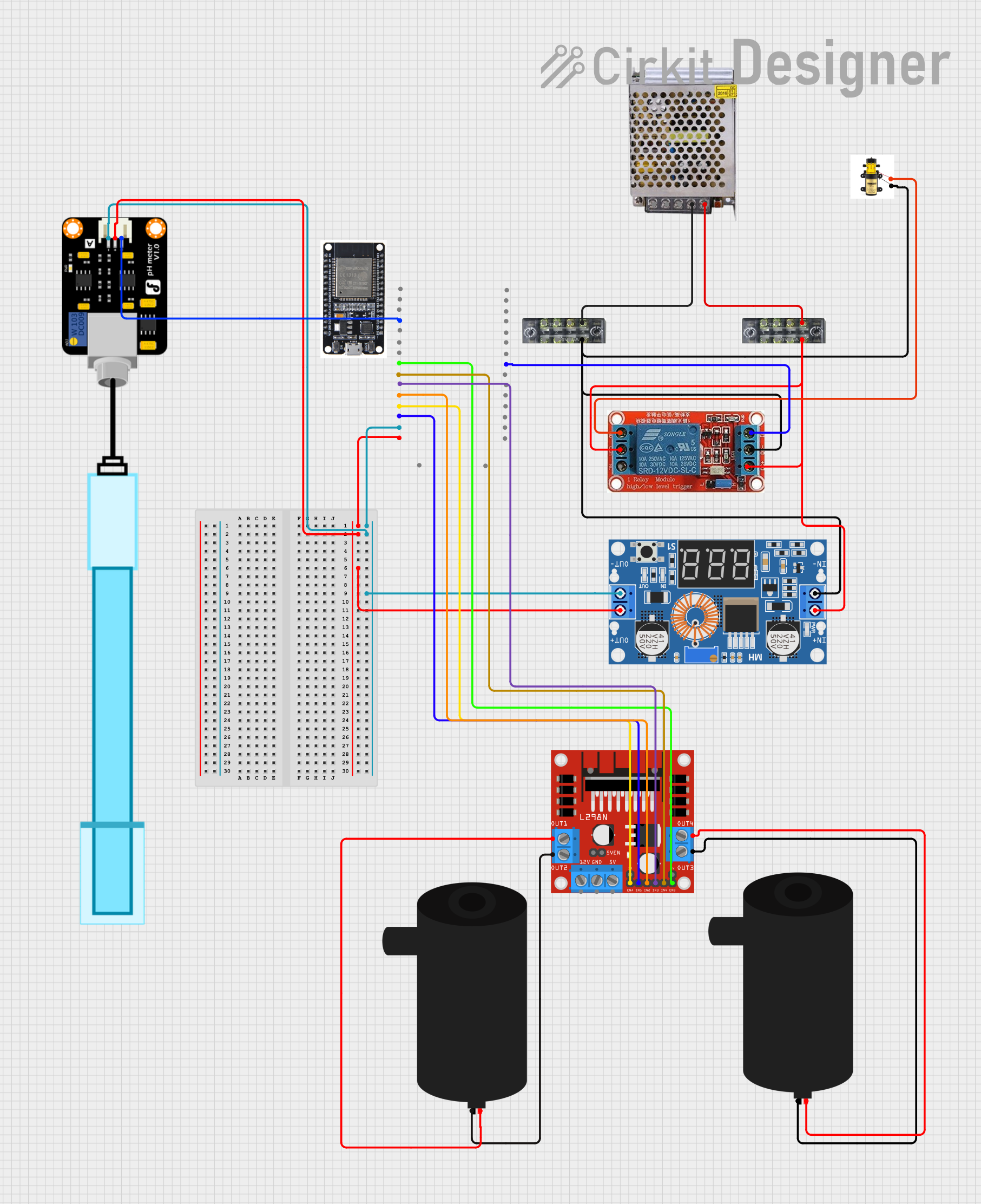
This document provides a detailed overview of a circuit designed to control a water pump and measure pH levels using an ESP32 microcontroller. The circuit includes various components such as a power supply, a DC motor driver, a relay, and a pH meter. The ESP32 microcontroller is programmed to read pH values and control the water pump based on the readings.
Component List
Pump
- Description: A generic pump used for water circulation.
- Pins: +, -
POWER SUPPLY 5V 5AMP
- Description: Provides 5V DC power with a maximum current of 5A.
- Pins: 220V Positive Pole (AC), 220V Negative Pole (AC), GND, GND (DC), 12V-24V Output (DC)
XL4015 5A DC Buck Step-down
- Description: A DC-DC buck converter capable of stepping down voltage with a maximum current of 5A.
- Pins: Output +, Output -, Input +, Input -
Terminal Block
- Description: A terminal block for connecting multiple wires.
- Pins: 1, 2, 3, 4, 5, 6, 7, 8
12V Relay
- Description: A relay used to control high-power devices.
- Pins: NO, COM, NC, IN, DC-, DC+
PH Meter
- Description: A sensor used to measure the pH level of a solution.
- Pins: Signal, VCC, GND
L298N DC Motor Driver
- Description: A motor driver used to control DC motors.
- Pins: OUT1, OUT2, 12V, GND, 5V, OUT3, OUT4, 5V-ENA-JMP-I, 5V-ENA-JMP-O, +5V-J1, +5V-J2, ENA, IN1, IN2, IN3, IN4, ENB
Water Pump
- Description: A generic water pump.
- Pins: positive, negative
ESP32
- Description: A microcontroller with built-in Wi-Fi and Bluetooth capabilities.
- Pins: EN, VP, VN, D34, D35, D32, D33, D25, D26, D27, D14, D12, D13, GND, VIN, 3V3, D15, D2, D4, RX2, TX2, D5, D18, D19, D21, RX0, TX0, D22, D23, BOOT
Wiring Details
Pump
- + connected to NO of 12V Relay
- - connected to Input - of XL4015 5A DC Buck Step-down and DC- of 12V Relay and 8 of Terminal Block
POWER SUPPLY 5V 5AMP
- GND (DC) connected to 7 of Terminal Block
- 12V-24V Output (DC) connected to 7 of Terminal Block
XL4015 5A DC Buck Step-down
- Output + connected to VIN of ESP32 and VCC of PH Meter
- Output - connected to GND of ESP32 and GND of PH Meter
- Input + connected to 8 of Terminal Block and COM of 12V Relay and DC+ of 12V Relay
Terminal Block
- 7 connected to GND (DC) of POWER SUPPLY 5V 5AMP
- 8 connected to Input + of XL4015 5A DC Buck Step-down and COM of 12V Relay and DC+ of 12V Relay
12V Relay
- IN connected to D5 of ESP32
- NO connected to + of Pump
- DC- connected to - of Pump and Input - of XL4015 5A DC Buck Step-down and 8 of Terminal Block
- COM connected to 8 of Terminal Block and Input + of XL4015 5A DC Buck Step-down
- DC+ connected to 8 of Terminal Block and Input + of XL4015 5A DC Buck Step-down
PH Meter
- Signal connected to D34 of ESP32
- VCC connected to Output + of XL4015 5A DC Buck Step-down
- GND connected to Output - of XL4015 5A DC Buck Step-down
L298N DC Motor Driver
- ENB connected to D25 of ESP32
- IN4 connected to D26 of ESP32
- IN3 connected to D27 of ESP32
- IN2 connected to D14 of ESP32
- ENA connected to D12 of ESP32
- IN1 connected to D13 of ESP32
- OUT1 connected to positive of Water Pump
- OUT2 connected to negative of Water Pump
- OUT3 connected to negative of Water Pump
- OUT4 connected to positive of Water Pump
Water Pump
- positive connected to OUT1 of L298N DC Motor Driver
- negative connected to OUT2 of L298N DC Motor Driver
- negative connected to OUT3 of L298N DC Motor Driver
- positive connected to OUT4 of L298N DC Motor Driver
ESP32
- VIN connected to Output + of XL4015 5A DC Buck Step-down
- GND connected to Output - of XL4015 5A DC Buck Step-down
- D34 connected to Signal of PH Meter
- D25 connected to ENB of L298N DC Motor Driver
- D26 connected to IN4 of L298N DC Motor Driver
- D27 connected to IN3 of L298N DC Motor Driver
- D14 connected to IN2 of L298N DC Motor Driver
- D12 connected to ENA of L298N DC Motor Driver
- D13 connected to IN1 of L298N DC Motor Driver
- D5 connected to IN of 12V Relay
Documented Code
ESP32 Code
#define PH_SENSOR_PIN 34  // Pin analog ESP32 (Po terhubung ke sini)

// Variabel pembacaan sensor
float sensorValue;
float voltage;
float pHValue;

// Kalibrasi sensor pH
const float VREF = 3.3;                    // Tegangan referensi ADC ESP32
const float calibration_offset = 0.00;     // Offset kalibrasi (sesuaikan)
const float slope = -5.70;                 // Kemiringan tegangan sensor pH

void setup() {
  Serial.begin(115200);       // Memulai komunikasi serial
  analogReadResolution(12);   // Resolusi 12-bit ADC (0-4095)
  Serial.println("Pembacaan Sensor pH dari Pin Po...");
}

void loop() {
  // Membaca nilai dari pin analog Po
  sensorValue = analogRead(PH_SENSOR_PIN);

  // Mengonversi nilai ADC ke tegangan
  voltage = sensorValue * (VREF / 4095.0);

  // Menghitung nilai pH berdasarkan tegangan
  pHValue = 7 + ((2.5 - voltage) / slope) + calibration_offset;

  // Menampilkan hasil di serial monitor
  Serial.print("Nilai ADC: ");
  Serial.print(sensorValue);
  Serial.print(" | Tegangan: ");
  Serial.print(voltage, 2);
  Serial.print(" V | Nilai pH: ");
  Serial.println(pHValue, 2);

  delay(1000);  // Delay 1 detik
}
XL4015 5A DC Buck Step-down Code
void setup() {
  // put your setup code here, to run once:

}

void loop() {
  // put your main code here, to run repeatedly:

}
This documentation provides a comprehensive overview of the circuit, including the components used, their wiring details, and the code for the microcontrollers.