Cirkit Designer
Your all-in-one circuit design IDE
Home /
Project Documentation
Arduino UNO Based Air Freshener Control System with Wi-Fi Connectivity and Motion Detection
Circuit Documentation
Summary
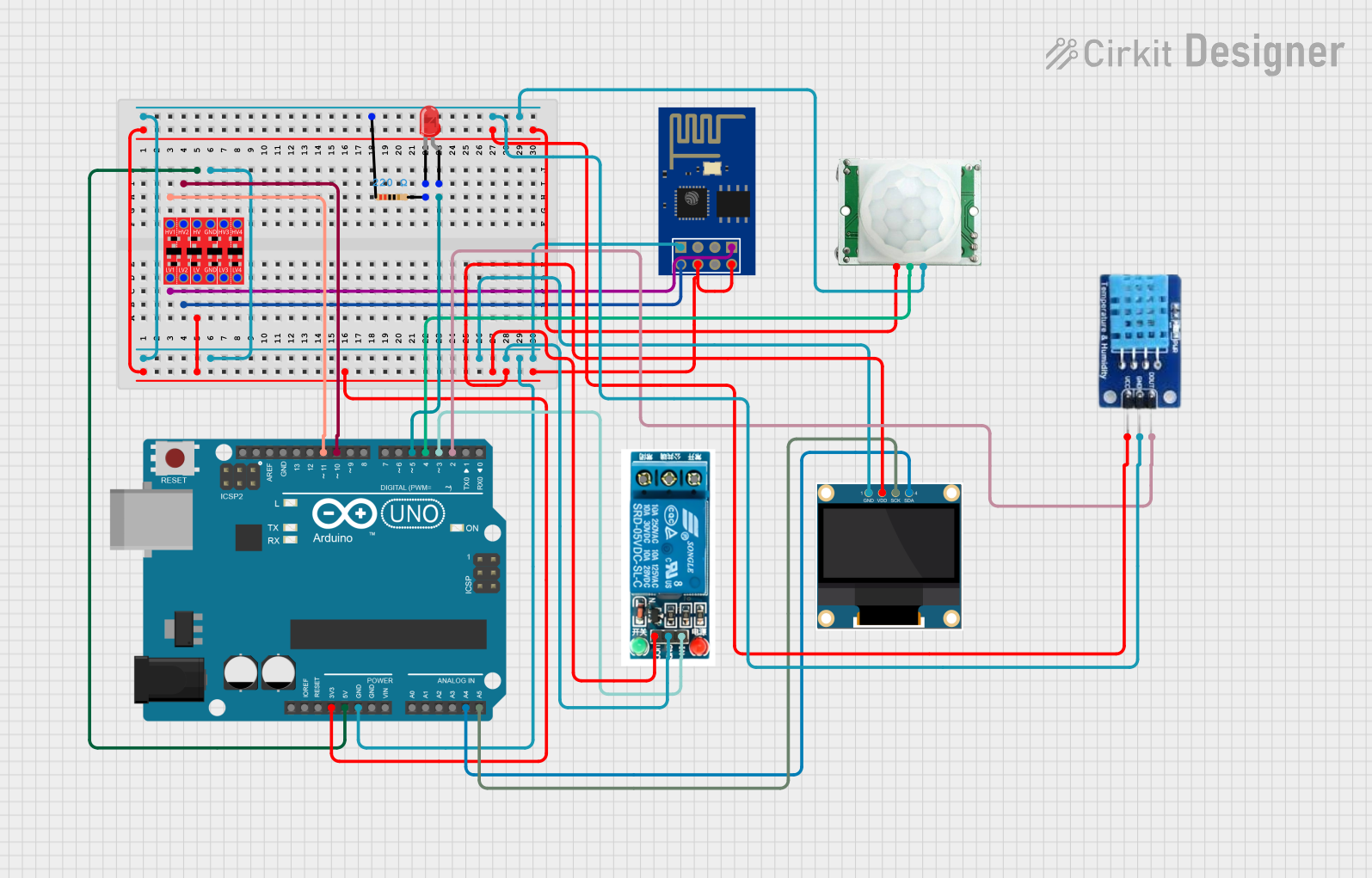
The circuit is designed to control an air freshener system using an Arduino UNO as the main controller. It features a DHT11 sensor for measuring temperature and humidity, a 0.96" OLED display for outputting sensor data, an ESP8266 ESP-01 WiFi module for network connectivity, a PIR (Motion Sensor) for detecting motion, a 5V relay for controlling the air freshener dispensing motor, a bi-directional logic level converter for voltage level translation between 3.3V and 5V devices, and an LED with a resistor to indicate system status. The system's behavior is programmed into the Arduino UNO, which interacts with the other components to display sensor readings, control the relay, and communicate with the ESP8266 for web-based control.
Component List
Arduino UNO
- Microcontroller board based on the ATmega328P
- Used as the main controller for the system
5V Relay
- Electromechanical switch used to control the air freshener dispensing motor
0.96" OLED
- Small display for showing temperature and humidity readings
ESP8266 ESP-01 WiFi Module
- WiFi module that enables network connectivity and hosts a web page for system control
PIR/Motion Sensor
- Sensor that detects motion and triggers the system to respond accordingly
DHT11
- Sensor for measuring temperature and humidity
Bi-Directional Logic Level Converter
- Device that safely steps down 5V signals to 3.3V and steps up 3.3V to 5V
LED: Two Pin (red)
- Indicator light that shows system status
Resistor
- 220 Ohm resistor used to limit current to the LED
Wiring Details
Arduino UNO
3.3Vconnected to the logic level converter LV, relay VCC, OLED VDD, ESP8266 CH_PD and VCC, DHT11 VCC, and PIR sensor VCC5Vconnected to the logic level converter HVGNDconnected to the resistor, logic level converter GND, OLED GND, relay GND, ESP8266 GND, DHT11 GND, and PIR sensor GNDA4 (SDA)connected to OLED SDAA5 (SCL)connected to OLED SCKD11connected to logic level converter HV1D10connected to logic level converter HV2D5connected to LED anodeD4connected to PIR sensor OUTPUTD3connected to relay InD2connected to DHT11 DATA
5V Relay
Inconnected to Arduino UNO D3GNDconnected to Arduino UNO GNDVCCconnected to Arduino UNO 3.3V
0.96" OLED
SDAconnected to Arduino UNO A4SCKconnected to Arduino UNO A5GNDconnected to Arduino UNO GNDVDDconnected to Arduino UNO 3.3V
ESP8266 ESP-01 WiFi Module
RXDconnected to logic level converter LV1TXDconnected to logic level converter LV2CH_PDandVCCconnected to Arduino UNO 3.3VGNDconnected to Arduino UNO GND
PIR/Motion Sensor
OUTPUTconnected to Arduino UNO D4GNDconnected to Arduino UNO GNDVCCconnected to Arduino UNO 3.3V
DHT11
DATAconnected to Arduino UNO D2GNDconnected to Arduino UNO GNDVCCconnected to Arduino UNO 3.3V
Bi-Directional Logic Level Converter
HVconnected to Arduino UNO 5VGNDconnected to Arduino UNO GNDHV1connected to Arduino UNO D11HV2connected to Arduino UNO D10LVconnected to Arduino UNO 3.3VLV1connected to ESP8266 RXDLV2connected to ESP8266 TXD
LED: Two Pin (red)
anodeconnected to Arduino UNO D5cathodeconnected to one end of the resistor
Resistor
- One end connected to LED cathode
- Other end connected to Arduino UNO GND
Documented Code
/*
 * Air Freshener Control System
 *
 * This code reads temperature and humidity from a DHT11 sensor and displays
 * the values on an OLED display and a web page hosted by an ESP8266 module.
 * An LED blinks every 2 seconds to indicate no motion and stays on when
 * motion is detected by a PIR sensor. The relay module controls the air
 * freshener dispensing motor, and the dispensing interval can be set via
 * the web page.
 */

#include <Wire.h>
#include <Adafruit_GFX.h>
#include <Adafruit_SSD1306.h>
#include <DHT.h>

#define DHTPIN 2         // Define the pin connected to the DHT11 data pin
#define DHTTYPE DHT11    // Specify the type of DHT sensor
#define LED_PIN 5        // Define the pin connected to the LED
#define PIR_PIN 4        // Define the pin connected to the PIR sensor output
#define RELAY_PIN 3      // Define the pin connected to the relay input
#define SCREEN_WIDTH 128 // OLED display width in pixels
#define SCREEN_HEIGHT 64 // OLED display height in pixels

DHT dht(DHTPIN, DHTTYPE); // Initialize the DHT sensor
Adafruit_SSD1306 display(SCREEN_WIDTH, SCREEN_HEIGHT, &Wire, -1); // Initialize the OLED display

unsigned long previousMillis = 0; // Stores the last time the LED was updated
const long interval = 2000;       // Interval at which to blink the LED (milliseconds)
bool motionDetected = false;      // Flag for motion detection

void setup() {
  pinMode(LED_PIN, OUTPUT);    // Set the LED pin as an output
  pinMode(PIR_PIN, INPUT);     // Set the PIR sensor pin as an input
  pinMode(RELAY_PIN, OUTPUT);  // Set the relay pin as an output
  digitalWrite(RELAY_PIN, LOW); // Ensure the relay is off at startup
  dht.begin();                 // Start the DHT sensor
  display.begin(SSD1306_SWITCHCAPVCC, 0x3C); // Initialize the OLED display with the I2C address
  display.display();           // Show the display buffer on the screen
  delay(2000);                 // Wait for 2 seconds
  display.clearDisplay();      // Clear the display buffer

  Serial.begin(115200); // Start serial communication with ESP8266 at 115200 baud
  // Initialize ESP8266
  Serial.println("AT+RST"); // Reset the ESP8266
  delay(1000);
  Serial.println("AT+CWMODE=1"); // Set ESP8266 to Station mode
  delay(1000);
  Serial.print("AT+CWJAP=\"your_SSID\",\"your_PASSWORD\""); // Connect to WiFi network
  delay(5000);
  Serial.println("AT+CIPMUX=1"); // Enable multiple connections
  delay(1000);
  Serial.println("AT+CIPSERVER=1,80"); // Start the server on port 80
  delay(1000);
}

void loop() {
  unsigned long currentMillis = millis(); // Get the current time
  if (digitalRead(PIR_PIN) == HIGH) { // Check if motion is detected
    motionDetected = true;
    digitalWrite(LED_PIN, HIGH); // Turn on the LED
  } else {
    motionDetected = false;
    if (currentMillis - previousMillis >= interval) { // Check if it's time to blink the LED
      previousMillis = currentMillis;
      digitalWrite(LED_PIN, !digitalRead(LED_PIN)); // Toggle the LED state
    }
  }
  float h = dht.readHumidity();    // Read humidity from DHT11
  float t = dht.readTemperature(); // Read temperature from DHT11
  display.clearDisplay();          // Clear the display buffer
  display.setTextSize(1);          // Set text size to 1
  display.setTextColor(SSD1306_WHITE); // Set text color to white
  display.setCursor(0, 0);         // Set cursor to top-left corner
  display.print("Temp: ");         // Print the temperature label
  display.print(t);                // Print the temperature value
  display.print(" C");             // Print the temperature unit
  display.setCursor(0, 10);        // Move cursor to the next line
  display.print("Humidity: ");     // Print the humidity label
  display.print(h);                // Print the humidity value
  display.print(" %");             // Print the humidity unit
  display.display();               //