
Arduino Uno-Based Environmental Monitoring System with LCD and LED Indicators
View and Edit Project In Cirkit Designer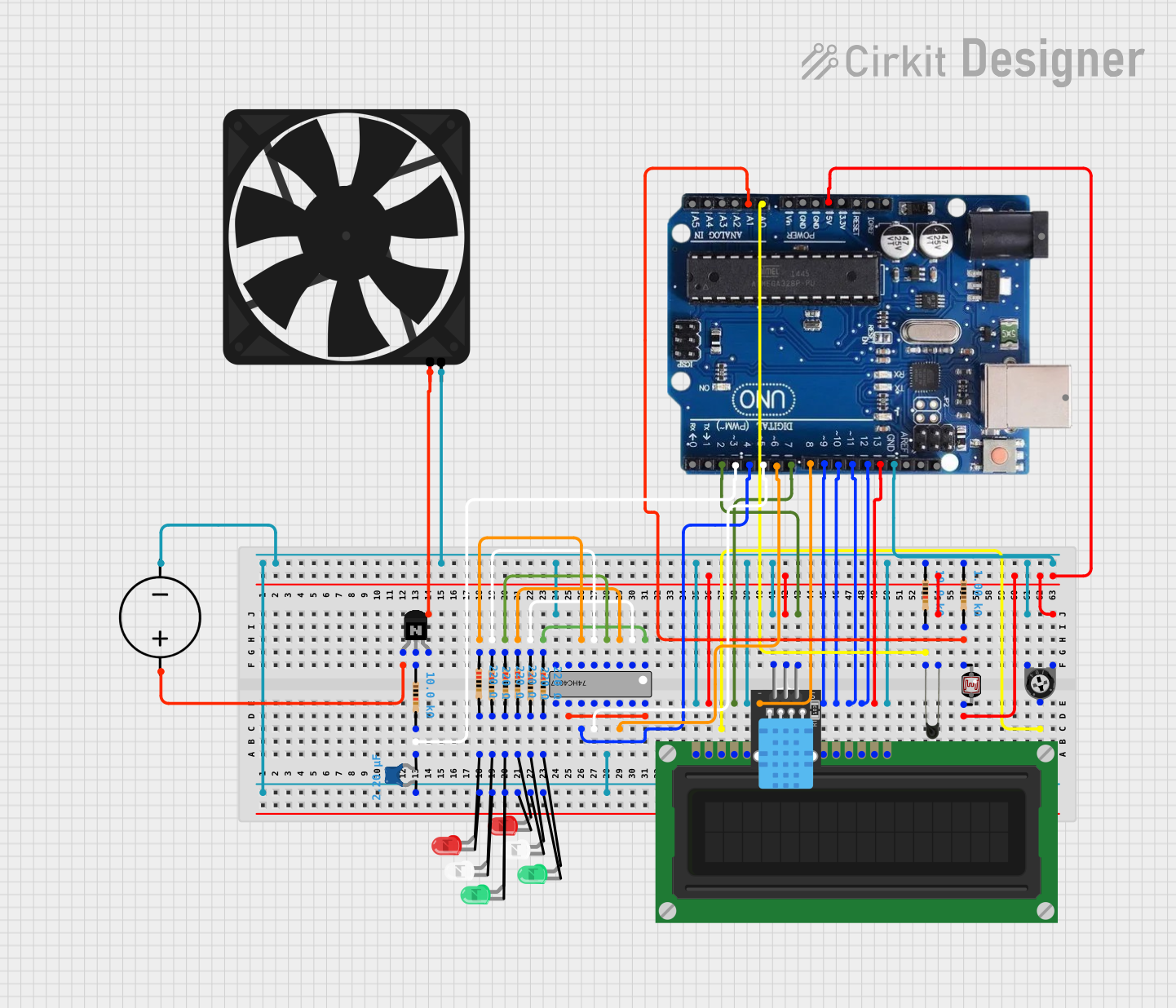
Circuit Documentation
Summary
This circuit appears to be a multifunctional system incorporating an Arduino Uno R3 as the central processing unit. It includes a variety of components such as LEDs, a fan, an LCD display, a DHT11 temperature and humidity sensor, a 74HC4017 decade counter, a trimmer potentiometer, an NTC thermistor, a photocell (LDR), and a DC power source. The circuit likely serves as a demonstration or educational platform for various electronic concepts, including digital and analog input/output, display interfacing, temperature sensing, and control of power devices like a fan.
Component List
- Arduino Uno R3: A microcontroller board based on the ATmega328P, featuring digital and analog I/O pins.
- DC Power Source: Provides power to the circuit.
- Fan: An electric fan powered by the circuit, possibly for cooling or demonstration of PWM control.
- LCD Display (16 pin): A 16-pin liquid crystal display for outputting text or numbers.
- Trimmer Potentiometer: A variable resistor, likely used for adjusting contrast on the LCD or as an analog input.
- NTC Thermistor: A temperature-sensitive resistor, used for measuring temperature changes.
- Resistors: Various resistors with different resistance values, used for current limiting and voltage division.
- Photocell (LDR): A light-dependent resistor, used for measuring light intensity.
- DHT11: A sensor for measuring ambient temperature and humidity.
- 74HC4017 Decade Counter: A counter/divider IC, used for creating sequential logic.
- LEDs (Red, Green, White): Light-emitting diodes used as visual indicators.
- NPN Transistor (EBC): A bipolar junction transistor, likely used as a switch or amplifier.
- Ceramic Capacitor: A capacitor used for noise filtering or timing applications.
Wiring Details
Arduino Uno R3
- GND connected to the common ground net.
- Pins 2, 3, 4, 5, 6, 7, 8, 9, 10, 11, 12, 13, A0, and A1 are connected to various components for control and sensing.
DC Power Source
- Positive terminal connected to the emitter of the NPN transistor.
- Ground terminal connected to the common ground net.
Fan
- 5V connected to the collector of the NPN transistor.
- GND connected to the common ground net.
LCD Display (16 pin)
- VSS, R_W, and K connected to the common ground net.
- VDD connected to the common ground net through various components.
- VO connected to the wiper of the trimmer potentiometer.
- RS, E, DB4, DB5, DB6, DB7, and A connected to various Arduino Uno R3 pins.
Trimmer Potentiometer
- Leg1 connected to the common ground net through various components.
- Wiper connected to the VO pin of the LCD display.
- Leg2 connected to the common ground net.
NTC Thermistor
- A0 connected to the A0 pin of the Arduino Uno R3.
- A1 connected to the common ground net through a resistor.
Photocell (LDR)
- Pin 0 connected to the A1 pin of the Arduino Uno R3.
- Pin 1 connected to the common ground net through a resistor.
DHT11
- 5V connected to the pin 2 of the Arduino Uno R3.
- S connected to the common ground net through various components.
- GND connected to the common ground net.
74HC4017 Decade Counter
- Q0, Q1, Q2, Q5, Q6, Q7, Q9, CP0, ~CP1, ~Q5-9, VCC, and GND connected to various Arduino Uno R3 pins or the common ground net.
LEDs (Red, Green, White)
- Cathodes connected to the common ground net.
- Anodes connected to the common ground net through a resistor.
NPN Transistor (EBC)
- Emitter connected to the positive terminal of the DC power source.
- Base connected to the common ground net through a resistor.
- Collector connected to the 5V pin of the fan.
Ceramic Capacitor
- One pin connected to the common ground net through a resistor.
- The other pin connected to pin 3 of the Arduino Uno R3.
Documented Code
No code was provided for the microcontrollers in the circuit. Therefore, this section is left blank until the relevant code is supplied. The code would typically include setup and loop functions for the Arduino Uno R3, detailing how it interacts with the connected sensors, displays, and other components.