Cirkit Designer
Your all-in-one circuit design IDE
Home /
Project Documentation
Arduino Nano Controlled LED Display and Relay System
Circuit Documentation
Summary
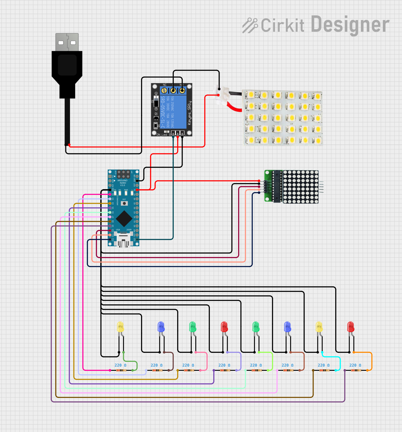
This document provides a detailed overview of a circuit that includes an Arduino Nano as the central microcontroller, interfaced with an 8x8 LED matrix, a USB power source, an LED board, a 1-Channel Relay, and multiple single LEDs of various colors. The circuit is designed to control the LED matrix and individual LEDs, with the capability to switch power to the LED board via the relay. The Arduino Nano is programmed to control the behavior of the LEDs and the relay.
Component List
Arduino Nano
- Microcontroller board based on the ATmega328P
- Pins: D1/TX, D0/RX, RESET, GND, D2 to D13/SCK, VIN, 5V, A0 to A7, AREF, 3V3
8x8 LED Matrix
- A matrix of 64 LEDs arranged in an 8x8 grid
- Pins: VCC, GND, DIN, CS, CLK
USB Connector
- Provides power to the circuit
- Pins: VCC, GND
LED Board
- A board with multiple LEDs
- Pins: VCC, GND
1-Channel Relay (5V 10A)
- A relay module for controlling high power devices
- Pins: NC, Signal, C, Power, NO, Ground
LEDs (Blue, Red, Green, Yellow)
- Single LEDs of various colors
- Pins: Cathode, Anode
Resistors (220 Ohms)
- Resistors used to limit current to the LEDs
- Resistance: 220 Ohms
Wiring Details
Arduino Nano
- GND connected to the cathodes of all single LEDs and the GND of the 8x8 LED matrix
- D2 to D9 connected to the anodes of single LEDs through 220 Ohm resistors
- D10 connected to DIN of the 8x8 LED matrix
- D11/MOSI connected to CS of the 8x8 LED matrix
- D12/MISO connected to CLK of the 8x8 LED matrix
- 5V connected to VCC of the 8x8 LED matrix and power of the 1-Channel Relay
- D13/SCK connected to the signal of the 1-Channel Relay
8x8 LED Matrix
- VCC connected to 5V of Arduino Nano
- GND connected to GND of Arduino Nano
- DIN connected to D10 of Arduino Nano
- CS connected to D11/MOSI of Arduino Nano
- CLK connected to D12/MISO of Arduino Nano
USB Connector
- VCC connected to the LED Board VCC
- GND connected to the NO of the 1-Channel Relay
LED Board
- VCC connected to VCC of USB Connector
- GND connected to C of the 1-Channel Relay
1-Channel Relay (5V 10A)
- Ground connected to GND of Arduino Nano
- Power connected to 5V of Arduino Nano
- Signal connected to D13/SCK of Arduino Nano
- NO connected to GND of USB Connector
- C connected to GND of LED Board
LEDs (Blue, Red, Green, Yellow)
- Cathodes connected to GND of Arduino Nano
- Anodes connected to D2 to D9 of Arduino Nano through 220 Ohm resistors
Resistors (220 Ohms)
- One side connected to D2 to D9 of Arduino Nano
- Other side connected to the anodes of single LEDs
Documented Code
Arduino Nano Code (sketch.ino)
void setup() {
  // put your setup code here, to run once:

}

void loop() {
  // put your main code here, to run repeatedly:

}
Additional Notes (documentation.txt)
No additional code documentation was provided for the Arduino Nano.