
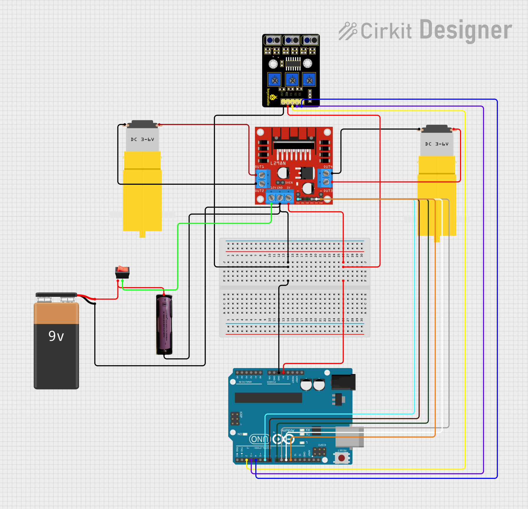
Circuit Documentation
Summary
This document provides a detailed overview of a circuit designed to control a robot using an Arduino UNO microcontroller. The circuit includes various components such as motors, a motor driver, a line tracking sensor, a rocker switch, and batteries. The Arduino UNO is programmed to read sensor inputs and control the motors accordingly.
Component List
Arduino UNO
- Description: A microcontroller board based on the ATmega328P.
- Pins: UNUSED, IOREF, Reset, 3.3V, 5V, GND, Vin, A0, A1, A2, A3, A4, A5, SCL, SDA, AREF, D13, D12, D11, D10, D9, D8, D7, D6, D5, D4, D3, D2, D1, D0
Motor amarillo motorreductor hobby
- Description: A small DC motor with a gearbox.
- Pins: vcc, GND
3 channel line tracking
- Description: A sensor module used for line tracking.
- Pins: GND, +VCC, S1, S2, S3
Rocker switch
- Description: A switch used to control the power supply.
- Pins: output, input
9V Battery
- Description: A 9V battery used as a power source.
- Pins: -, +
L298N DC motor driver
- Description: A dual H-Bridge motor driver.
- Pins: OUT1, OUT2, 12V, GND, 5V, OUT3, OUT4, 5V-ENA-JMP-I, 5V-ENA-JMP-O, +5V-J1, +5V-J2, ENA, IN1, IN2, IN3, IN4, ENB
3.7v Battery
- Description: A 3.7V battery used as an additional power source.
- Pins: +, -
Wiring Details
Arduino UNO
GND connected to:
- 3 channel line tracking (GND)
- 9V Battery (-)
- L298N DC motor driver (GND)
- 3.7v Battery (-)
5V connected to:
- 3 channel line tracking (+VCC)
- L298N DC motor driver (5V)
D11 connected to:
- L298N DC motor driver (ENB)
D10 connected to:
- L298N DC motor driver (IN4)
D9 connected to:
- L298N DC motor driver (IN3)
D8 connected to:
- L298N DC motor driver (IN2)
D7 connected to:
- L298N DC motor driver (IN1)
D6 connected to:
- L298N DC motor driver (ENA)
D4 connected to:
- 3 channel line tracking (S3)
D3 connected to:
- 3 channel line tracking (S2)
D2 connected to:
- 3 channel line tracking (S1)
Motor amarillo motorreductor hobby
vcc connected to:
- L298N DC motor driver (OUT1)
- L298N DC motor driver (OUT3)
GND connected to:
- L298N DC motor driver (OUT2)
- L298N DC motor driver (OUT4)
3 channel line tracking
GND connected to:
- Arduino UNO (GND)
+VCC connected to:
- Arduino UNO (5V)
S1 connected to:
- Arduino UNO (D2)
S2 connected to:
- Arduino UNO (D3)
S3 connected to:
- Arduino UNO (D4)
Rocker switch
output connected to:
- L298N DC motor driver (12V)
input connected to:
- 9V Battery (+)
- 3.7v Battery (+)
9V Battery
- connected to:
- Arduino UNO (GND)
- 3 channel line tracking (GND)
- L298N DC motor driver (GND)
- 3.7v Battery (-)
+ connected to:
- Rocker switch (input)
L298N DC motor driver
GND connected to:
- Arduino UNO (GND)
- 9V Battery (-)
- 3.7v Battery (-)
5V connected to:
- Arduino UNO (5V)
- 3 channel line tracking (+VCC)
12V connected to:
- Rocker switch (output)
OUT1 connected to:
- Motor amarillo motorreductor hobby (vcc)
OUT2 connected to:
- Motor amarillo motorreductor hobby (GND)
OUT3 connected to:
- Motor amarillo motorreductor hobby (vcc)
OUT4 connected to:
- Motor amarillo motorreductor hobby (GND)
ENA connected to:
- Arduino UNO (D6)
IN1 connected to:
- Arduino UNO (D7)
IN2 connected to:
- Arduino UNO (D8)
IN3 connected to:
- Arduino UNO (D9)
IN4 connected to:
- Arduino UNO (D10)
ENB connected to:
- Arduino UNO (D11)
3.7v Battery
+ connected to:
- Rocker switch (input)
- connected to:
- Arduino UNO (GND)
- 3 channel line tracking (GND)
- 9V Battery (-)
- L298N DC motor driver (GND)
Code Documentation
// กำหนด pin
const int Sensor1 = 2;
const int Sensor2 = 3;
const int Sensor3 = 4;

const int EnB_PWM = 6;
const int(IN1) = 7;
const int IN2 = 8;
const int IN3 = 9;
const int IN4 = 10;
const int EnA_PWM = 11;

void setup() {
  // กำหนดเซ็นเซอร์ 3 ตัว
  pinMode(Sensor1, INPUT);
  pinMode(Sensor2, INPUT);
  pinMode(Sensor3, INPUT);

  // กำหนดมอเตอร์ 4 ตัว
  pinMode(IN1, OUTPUT);
  pinMode(IN2, OUTPUT);
  pinMode(IN3, OUTPUT);
  pinMode(IN4, OUTPUT);

  // ควบคุมความเร็วมอเตอร์
  pinMode(EnA_PWM, OUTPUT);
  pinMode(EnB_PWM, OUTPUT);

  stopMotors();
}

void loop() {

  int sensor1 = digitalRead(Sensor1);
  int sensor2 = digitalRead(Sensor2);
  int sensor3 = digitalRead(Sensor3);

  if (sensor2 == LOW && sensor3 == LOW) {
    // Move forward
    moveForward();
  } else if (sensor1 == HIGH) {
    // Turn right
    turnRight();
  } else if (sensor4 == HIGH) {
    // Turn left
    turnLeft();
  } else {
    // Stop if no clear path
    stopMotors();
  }
}

void moveForward() {
  digitalWrite(IN1, HIGH);
  digitalWrite(IN2, LOW);
  digitalWrite(IN3, HIGH);
  digitalWrite(IN4, LOW);
  analogWrite(EnA_PWM, 255);
  analogWrite(EnB_PWM, 255);
}

void turnRight() {
  digitalWrite(IN1, LOW);
  digitalWrite(IN2, HIGH);
  digitalWrite(IN3, HIGH);
  digitalWrite(IN4, LOW);
  analogWrite(EnA_PWM, 255);
  analogWrite(EnB_PWM, 255);
}

void turnLeft() {
  digitalWrite(IN1, HIGH);
  digitalWrite(IN2, LOW);
  digitalWrite(IN3, LOW);
  digitalWrite(IN4, HIGH);
  analogWrite(EnA_PWM, 255);
  analogWrite(EnB_PWM, 255);
}

void stopMotors() {
  digitalWrite(IN1, LOW);
  digitalWrite(IN2, LOW);
  digitalWrite(IN3, LOW);
  digitalWrite(IN4, LOW);
  analogWrite(EnA_PWM, 0);
  analogWrite(EnB_PWM, 0);
}
This code is written for the Arduino UNO microcontroller. It initializes the pins for the sensors and motors, reads the sensor inputs, and controls the motors to move the robot forward, turn left, or turn right based on the sensor readings. The stopMotors function is used to stop the motors when no clear path is detected.