
ESP32-Based Smart Humidity and Temperature Controller with Wi-Fi Connectivity
View and Edit Project In Cirkit Designer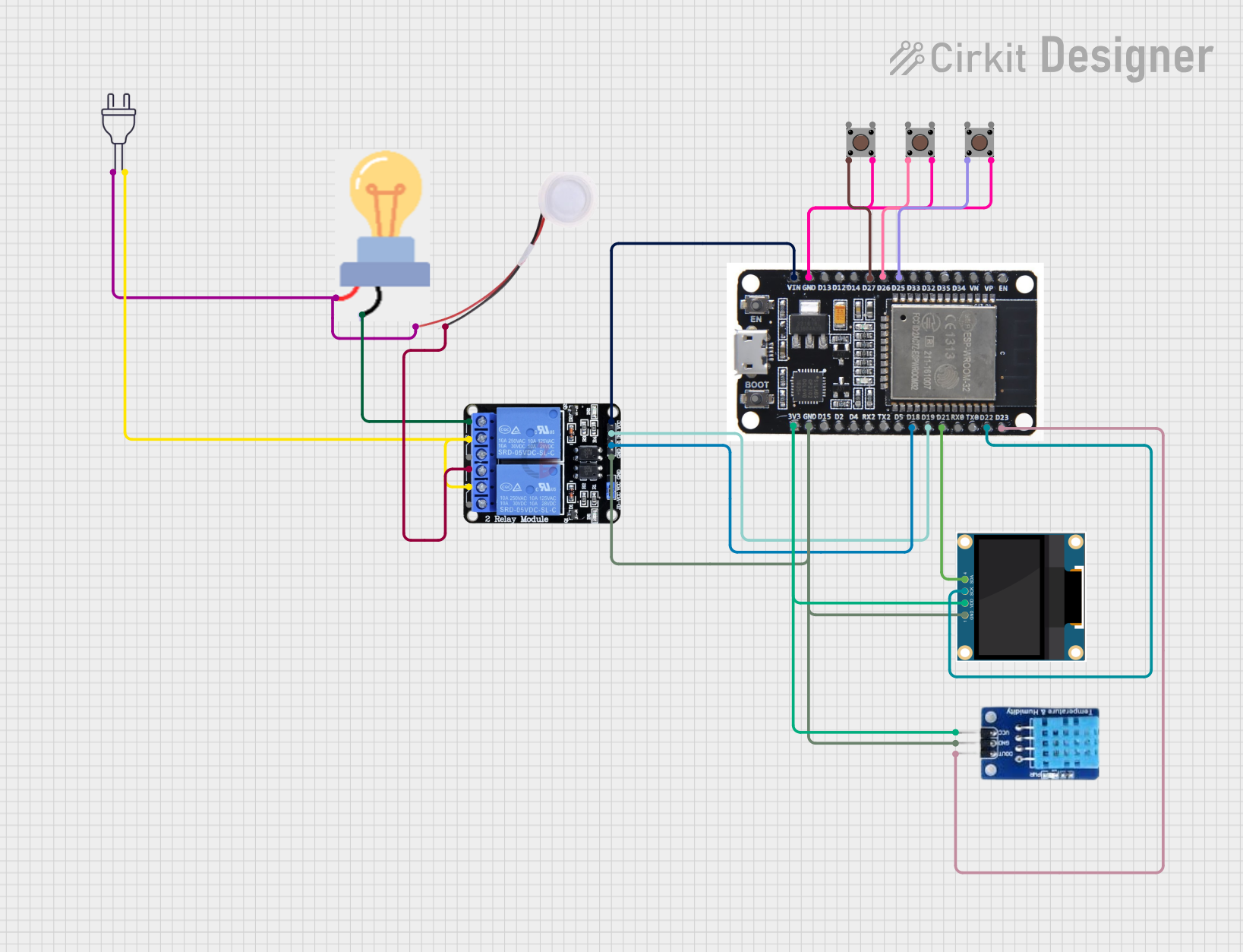
Circuit Documentation
Summary
The circuit in question is designed to control a humidifier and a bulb using an ESP32 microcontroller. The system includes a DHT11 sensor for measuring temperature and humidity, a 0.96" OLED display for user interface, two pushbuttons for manual control, and a two-channel relay to switch the humidifier and bulb. The ESP32 is connected to the internet and uses Blynk for remote monitoring and control. The circuit is powered by a 220V power source, and the components are interconnected through various electrical nets to ensure proper functionality.
Component List
Humidifier
- Description: A device that adds moisture to the air.
- Purpose: To be controlled by the ESP32 to maintain desired humidity levels.
0.96" OLED
- Description: A small display to provide a user interface.
- Purpose: To display temperature, humidity, and system status.
Two Channel Relay 5V
- Description: An electromechanical switch with two channels.
- Purpose: To control the power to the humidifier and bulb.
Pushbutton (x3)
- Description: A simple switch that allows user input.
- Purpose: To provide manual control over the system.
Bulb
- Description: An electric light source.
- Purpose: To be controlled by the ESP32, possibly for indicating status or providing light.
Power 220V
- Description: A power source providing 220V AC.
- Purpose: To power the circuit components.
ESP32
- Description: A microcontroller with Wi-Fi capabilities.
- Purpose: To control the circuit, read sensor data, and communicate with Blynk.
DHT11
- Description: A basic, ultra low-cost digital temperature and humidity sensor.
- Purpose: To measure the temperature and humidity for the system.
Wiring Details
Humidifier
- 5V: Connected to the power source (220V hot wire).
- GND: Connected to the NC1 pin of the Two Channel Relay 5V.
0.96" OLED
- GND: Connected to the GND net shared with ESP32, DHT11, and Two Channel Relay 5V.
- VDD: Connected to the 3V3 output of the ESP32.
- SCK: Connected to the D22 pin of the ESP32.
- SDA: Connected to the D21 pin of the ESP32.
Two Channel Relay 5V
- VCC: Connected to the VIN pin of the ESP32.
- IN1: Connected to the D18 pin of the ESP32.
- IN2: Connected to the D19 pin of the ESP32.
- GND: Connected to the GND net shared with other components.
- NC1, NC2: Connected to the GND of the Humidifier and Bulb respectively.
- C1, C2: Connected to the neutral wire of the Power 220V.
Pushbuttons
- Pin 2 (in): Connected to the D25, D26, and D27 pins of the ESP32 for the three buttons respectively.
- Pin 4 (out): Connected to the GND net shared with other components.
Bulb
- Power: Connected to the power source (220V hot wire).
- GND: Connected to the NC2 pin of the Two Channel Relay 5V.
Power 220V
- Hot Wire: Connected to the power pins of the Humidifier and Bulb.
- Neutral Wire: Connected to the C1 and C2 pins of the Two Channel Relay 5V.
ESP32
- GND, 3V3, VIN, D21, D22, D18, D19, D25, D26, D27: Connected as described in the wiring details of other components.
DHT11
- DATA: Connected to the D23 pin of the ESP32.
- GND: Connected to the GND net shared with other components.
- VCC: Connected to the 3V3 output of the ESP32.
Documented Code
The code provided is for the ESP32 microcontroller and is responsible for controlling the circuit's functionality. It includes the Blynk library for IoT connectivity, the DHT sensor library for reading temperature and humidity, and the Adafruit SSD1306 library for the OLED display. The code handles Wi-Fi connection, Blynk server communication, sensor data reading, display updates, and relay control based on the sensor readings and user input from the pushbuttons.
// Code omitted for brevity. Please refer to the provided code input for the full source code.
The code initializes the hardware components, connects to Wi-Fi, and sets up Blynk for remote monitoring and control. It reads sensor data from the DHT11 sensor and displays it on the OLED. It also listens for button presses to toggle the mode, heater, and humidifier states, which are then synchronized with the Blynk app. The relays are controlled based on the current temperature and humidity readings compared to the setpoints, and the system can operate in either automatic or manual mode.