Arduino UNO Controlled Servo Gate with Ultrasonic Sensor and LED Indicators
Circuit Documentation
Summary
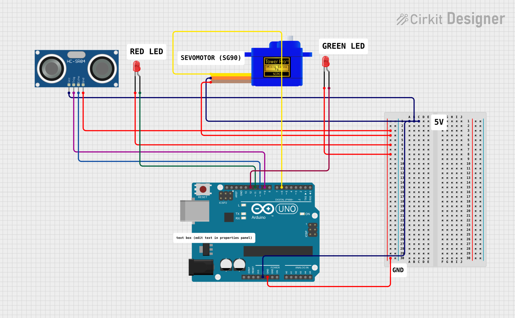
The circuit in question is designed around an Arduino UNO microcontroller and includes a variety of peripheral components. The primary function of this circuit is to utilize an HC-SR04 Ultrasonic Sensor to detect the presence of an object within a certain distance threshold and to respond by controlling a Servomotor SG90 and two LEDs. The Arduino UNO controls the logic and processing of sensor data, drives the servomotor, and manages the state of the LEDs based on the proximity of an object.
Component List
Arduino UNO
- Description: A microcontroller board based on the ATmega328P.
- Purpose: Acts as the central processing unit of the circuit, controlling the sensor, servomotor, and LEDs.
LED: Two Pin (red)
- Description: A basic red LED with an anode and cathode pin.
- Purpose: Provides visual indication of the system status.
Servomotor SG90
- Description: A small and lightweight servo motor capable of precise control.
- Purpose: Actuates a mechanism in response to sensor input.
HC-SR04 Ultrasonic Sensor
- Description: An ultrasonic distance sensor capable of measuring distances by emitting ultrasonic waves.
- Purpose: Detects the presence and distance of objects in front of the sensor.
Wiring Details
Arduino UNO
- 5V: Powers the HC-SR04 Ultrasonic Sensor and Servomotor SG90.
- GND: Common ground for the HC-SR04 Ultrasonic Sensor, Servomotor SG90, and both red LEDs.
- D12: Connected to the anode of one red LED.
- D11: Connected to the anode of the other red LED.
- D10: Connected to the ECHO pin of the HC-SR04 Ultrasonic Sensor.
- D9: Connected to the TRIG pin of the HC-SR04 Ultrasonic Sensor.
- D6: Connected to the SIG pin of the Servomotor SG90.
LED: Two Pin (red)
- Anode: Connected to either D12 or D11 on the Arduino UNO.
- Cathode: Connected to GND on the Arduino UNO.
Servomotor SG90
- SIG: Connected to D6 on the Arduino UNO.
- VCC: Connected to 5V on the Arduino UNO.
- GND: Connected to GND on the Arduino UNO.
HC-SR04 Ultrasonic Sensor
- VCC: Connected to 5V on the Arduino UNO.
- TRIG: Connected to D9 on the Arduino UNO.
- ECHO: Connected to D10 on the Arduino UNO.
- GND: Connected to GND on the Arduino UNO.
Documented Code
#include <Servo.h>

const int trigPin = 9;
const int echoPin = 10;
const int redLEDPin = 12;
const int greenLEDPin = 11;
const int servoPin = 6;

Servo gateServo;

const int distanceThreshold = 10;

void setup() {
  Serial.begin(9600);

  pinMode(trigPin, OUTPUT);
  pinMode(echoPin, INPUT);
  pinMode(redLEDPin, OUTPUT);
  pinMode(greenLEDPin, OUTPUT);

  gateServo.attach(servoPin);

  digitalWrite(redLEDPin, HIGH);
  digitalWrite(greenLEDPin, LOW);
  gateServo.write(0);
}

void loop() {

  long duration, distance;
  digitalWrite(trigPin, LOW);
  delay(1000);
  digitalWrite(trigPin, HIGH);
  delayMicroseconds(10);
  digitalWrite(trigPin, LOW);
  duration = pulseIn(echoPin, HIGH);
  distance = (duration / 2) / 29.1;

  if (distance < distanceThreshold) {
    digitalWrite(redLEDPin, LOW);
    digitalWrite(greenLEDPin, HIGH);
    gateServo.write(90);
  } else {
    digitalWrite(redLEDPin, HIGH);
    digitalWrite(greenLEDPin, LOW);
    gateServo.write(0);
  }

  delay(10);
}
Filename: sketch.ino
Description: This code initializes the Arduino UNO's serial communication and configures the pins connected to the HC-SR04 Ultrasonic Sensor, LEDs, and Servomotor SG90. In the main loop, the ultrasonic sensor measures the distance to an object. If the object is within the defined threshold, the red LED is turned off, the green LED is turned on, and the servomotor is moved to 90 degrees. If the object is outside the threshold, the red LED is turned on, the green LED is turned off, and the servomotor is returned to 0 degrees.