
Circuit Documentation
Summary of the Circuit
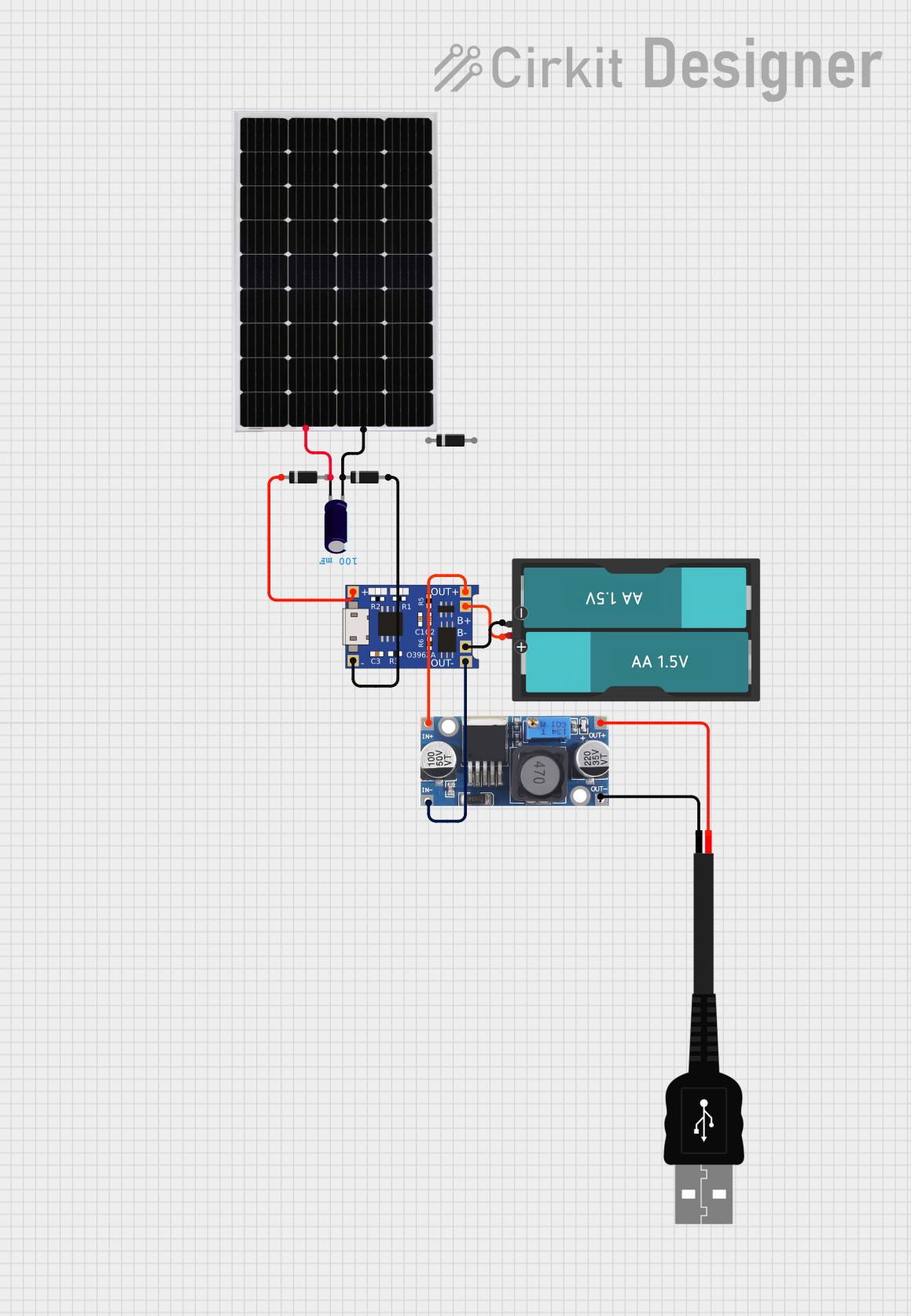
This circuit appears to be a power management system that uses a solar panel to charge a battery through a charging module (TP4056). It includes a voltage regulator to step down the voltage from 48V to 5V, which is then provided to a USB connection. Diodes are likely used for protection or to prevent backflow of current. An electrolytic capacitor is used for smoothing out voltage fluctuations. The absence of microcontroller code suggests that this circuit operates without programmable control logic.
Component List
Solar Panel
- Description: A photovoltaic panel that converts sunlight into electrical energy.
- Pins: Positive (+), Negative (-)
Electrolytic Capacitor
- Description: A capacitor used for filtering and stabilizing the DC power supply.
- Pins: Positive (+), Negative (-)
- Properties: Capacitance: 0.1 Farads
Diode
- Description: A semiconductor device that allows current to flow in one direction only.
- Pins: Anode, Cathode
Voltage Regulator (48v to 5v)
- Description: A device that converts a higher input voltage to a stable lower output voltage.
- Pins: Input Positive (in+), Input Negative (in--), Output Positive (out+), Output Negative (out--)
TP4056
- Description: A lithium battery charging module with battery protection.
- Pins: Battery Negative (B-), Battery Positive (B+), Output Negative (OUT-), Output Positive (OUT+), Input Negative (IN-), Input Positive (IN+)
Battery AAx2 3V
- Description: A standard 3V battery pack consisting of two AA batteries.
- Pins: VCC, GND
USB male 2 pin connection
- Description: A USB connector for providing power to USB devices.
- Pins: Positive (+), Negative (-)
Wiring Details
Solar Panel
- Positive (+) connected to the positive pin of the Electrolytic Capacitor.
- Negative (-) connected to the negative pin of the Electrolytic Capacitor.
Electrolytic Capacitor
- Positive (+) connected to the positive pin of the Solar Panel.
- Negative (-) connected to the negative pin of the Solar Panel.
Diodes
- Anode of one diode connected to the IN- pin of the TP4056.
- Cathode of another diode connected to the IN+ pin of the TP4056.
Voltage Regulator (48v to 5v)
- Input Positive (in+) connected to the OUT+ pin of the TP4056.
- Input Negative (in--) connected to the OUT- pin of the TP4056.
- Output Positive (out+) connected to the Positive (+) pin of the USB male 2 pin connection.
- Output Negative (out--) connected to the Negative (-) pin of the USB male 2 pin connection.
TP4056
- IN- connected to the anode of a Diode.
- IN+ connected to the cathode of another Diode.
- OUT- connected to the Input Negative (in--) of the Voltage Regulator.
- OUT+ connected to the Input Positive (in+) of the Voltage Regulator.
- B- connected to the GND pin of the Battery AAx2 3V.
- B+ connected to the VCC pin of the Battery AAx2 3V.
Battery AAx2 3V
- VCC connected to the B+ pin of the TP4056.
- GND connected to the B- pin of the TP4056.
USB male 2 pin connection
- Positive (+) connected to the Output Positive (out+) of the Voltage Regulator.
- Negative (-) connected to the Output Negative (out--) of the Voltage Regulator.
Documented Code
No code has been provided for any microcontrollers in the circuit. This section is therefore not applicable to the current documentation.