
Multifunctional IoT Device with GPS, GSM, Ultrasonic Sensing, and Audio-Visual Capabilities
View and Edit Project In Cirkit Designer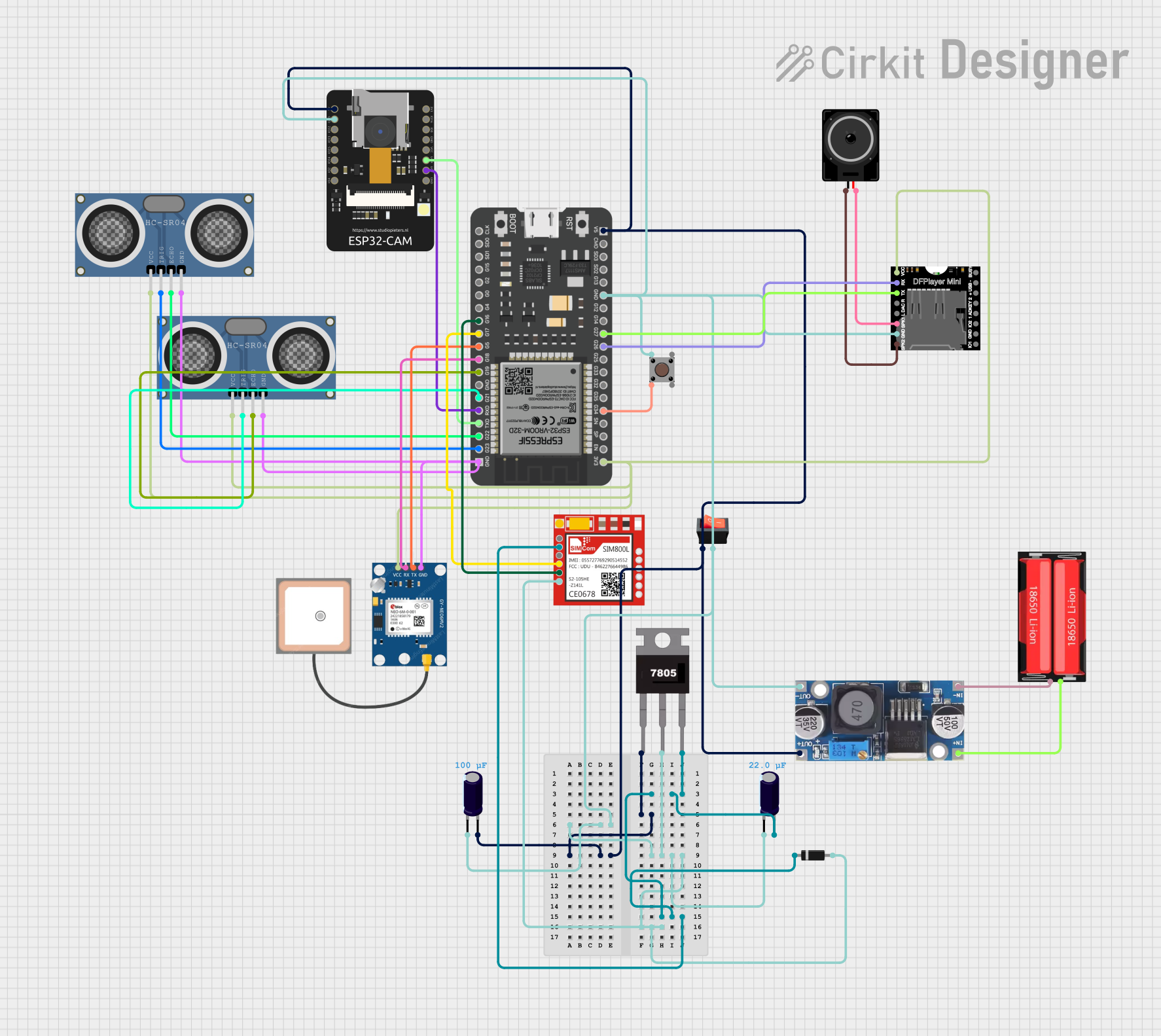
Circuit Documentation
Summary
This circuit is designed to integrate various components including power management, communication modules, sensors, and microcontrollers. The circuit features a 18650 Li-Ion battery as the power source, which is regulated by a step-down buck converter and a 7805 voltage regulator to provide stable power to the components. Communication capabilities are provided by a GPS NEO 6M module and a Sim800l GSM module. The ESP32-CAM and ESP32-38 pins microcontrollers serve as the central processing units, interfacing with sensors like the HC-SR04 Ultrasonic Distance Sensors and peripherals such as the DFPlayer MINI MP3 module and a loudspeaker. A rocker switch is used to control power flow, and pushbuttons provide user input. Diodes and electrolytic capacitors are used for protection and filtering purposes.
Component List
Power Components
- 18650 Li-Ion Battery: Provides the main power source for the circuit.
- Step-down Buck Converter: Converts the battery voltage to a lower, regulated voltage for the circuit.
- 7805 Voltage Regulator: Provides a stable 5V output from the input voltage.
- Electrolytic Capacitors: Used for voltage smoothing and filtering.
- Rocker Switch: Acts as an on/off switch for the circuit.
Communication Modules
- GPS NEO 6M: A GPS module for location tracking.
- Sim800l: A GSM module for cellular communication.
Microcontrollers
- ESP32-CAM: A microcontroller with integrated Wi-Fi and camera capabilities.
- ESP32 - 38 pins: A microcontroller with a wide range of GPIO pins for interfacing with various peripherals.
Sensors and Peripherals
- HC-SR04 Ultrasonic Distance Sensors: Measure distances using ultrasonic waves.
- DFPlayer MINI: An MP3 module for audio playback.
- Loudspeaker: Outputs audio signals from the DFPlayer MINI.
User Interface
- Pushbutton: Provides user input to the microcontrollers.
Protection
- Diode: Prevents reverse current flow which could damage the circuit.
Wiring Details
Power Components
18650 Li-Ion Battery
- Positive: Connected to the input of the Step-down Buck Converter.
- Negative: Connected to the ground input of the Step-down Buck Converter.
Step-down Buck Converter
- IN +: Connected to the positive terminal of the 18650 Li-Ion Battery.
- IN - GND: Connected to the negative terminal of the 18650 Li-Ion Battery.
- OUT +: Connected to the input of the 7805 Voltage Regulator, the rocker switch, and the 5V input of the ESP32-CAM and ESP32 - 38 pins.
- OUT - GND: Connected to the ground of the circuit.
7805 Voltage Regulator
- Vin: Connected to the output of the Step-down Buck Converter.
- Gnd: Connected to the ground of the circuit.
- Vout: Connected to the VCC of the Sim800l and the positive side of an Electrolytic Capacitor.
Electrolytic Capacitors
- Capacitor 1 (0.0001 Farads): Connected between the Vout of the 7805 and ground.
- Capacitor 2 (0.000022 Farads): Connected between the Vin of the 7805 and ground.
Rocker Switch
- Input: Connected to the OUT + of the Step-down Buck Converter.
- Output: Connected to the ground of the circuit.
Communication Modules
GPS NEO 6M
- VCC: Connected to the 3V3 output of the ESP32 - 38 pins.
- RX: Connected to the G18 pin of the ESP32 - 38 pins.
- TX: Connected to the G5 pin of the ESP32 - 38 pins.
- GND: Connected to the ground of the circuit.
Sim800l
- VCC: Connected to the Vout of the 7805 Voltage Regulator.
- RXD: Connected to the G17 pin of the ESP32 - 38 pins.
- TXD: Connected to the G16 pin of the ESP32 - 38 pins.
- GND: Connected to the ground of the circuit.
Microcontrollers
ESP32-CAM
- 5V: Connected to the OUT + of the Step-down Buck Converter.
- GND: Connected to the ground of the circuit.
- VOT: Connected to the RXD pin of the ESP32 - 38 pins.
- VOR: Connected to the TXD pin of the ESP32 - 38 pins.
ESP32 - 38 pins
- 3V3: Connected to the VCC of the GPS NEO 6M and HC-SR04 Ultrasonic Distance Sensors.
- GND: Connected to the ground of the circuit.
- Various GPIOs: Connected to the RX and TX pins of the GPS NEO 6M, Sim800l, DFPlayer MINI, and HC-SR04 Ultrasonic Distance Sensors.
Sensors and Peripherals
HC-SR04 Ultrasonic Distance Sensors
- VCC: Connected to the 3V3 output of the ESP32 - 38 pins.
- TRIG: Connected to the GPIO pins (G23, G21) of the ESP32 - 38 pins.
- ECHO: Connected to the GPIO pins (G22, G19) of the ESP32 - 38 pins.
- GND: Connected to the ground of the circuit.
DFPlayer MINI
- VCC: Connected to the 3V3 output of the ESP32 - 38 pins.
- RX: Connected to the G26 pin of the ESP32 - 38 pins.
- TX: Connected to the G27 pin of the ESP32 - 38 pins.
- GND: Connected to the ground of the circuit.
- SPK1: Connected to pin2 of the Loudspeaker.
- SPK2: Connected to pin1 of the Loudspeaker.
Loudspeaker
- pin1: Connected to the SPK2 of the DFPlayer MINI.
- pin2: Connected to the SPK1 of the DFPlayer MINI.
User Interface
- Pushbutton
- Pin 1 (in): Connected to the ground of the circuit.
- Pin 2 (in): Connected to the G34 pin of the ESP32 - 38 pins.
Protection
- Diode
- Cathode: Connected to the VCC of the Sim800l.
- Anode: Connected to the ground of the circuit.
Documented Code
No code has been provided for the microcontrollers in this circuit. The code would typically include initialization and configuration of the microcontroller's peripherals, communication protocols for the GPS and GSM modules, control logic for the sensors, and user interface management. Without the code, the functionality of the circuit cannot be fully described.