ESP8266 NodeMCU-Based Smart Eye Pressure Monitor with OLED Display and Wi-Fi Connectivity

Circuit Documentation
Summary
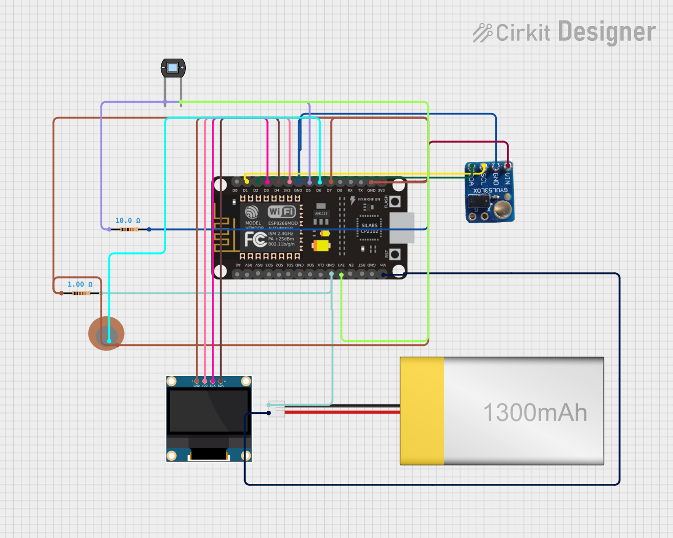
The circuit in question is designed to interface an ESP8266 NodeMCU microcontroller with a variety of sensors and an OLED display. The primary components include the ESP8266 NodeMCU, a VL53L0X time-of-flight distance sensor, a 0.96" OLED display, a piezo sensor, a photodiode, and two resistors. The circuit is powered by a LiPoly battery. The ESP8266 NodeMCU is programmed to read sensor data, classify pressure, display information on the OLED, and serve a webpage with the current pressure classification.
Component List
ESP8266 NodeMCU
- Microcontroller with WiFi capability.
- Pins: D0, D1, D2, D3, D4, 3V3, GND, D5, D6, D7, D8, RX, TX, A0, RSV, SD3, SD2, SD1, CMD, SD0, CLK, EN, RST, VIN.
VL53L0X Time-of-Flight Distance Sensor
- A laser-ranging module.
- Pins: vin, gnd, scl, sda.
LiPoly Battery (1300mAh)
- Rechargeable battery for power supply.
- Pins: positive, negative.
0.96" OLED Display
- Small screen for data display.
- Pins: GND, VDD, SCK, SDA.
Piezo Sensor
- Sensor for detecting vibrations and pressure changes.
- Pins: +, -.
Photodiode
- Light sensor that generates a voltage in response to light.
- Pins: cathode, anode.
Resistor (10 Ohms)
- A resistor with a resistance of 10 Ohms.
Resistor (1 Ohm)
- A resistor with a resistance of 1 Ohm.
Wiring Details
ESP8266 NodeMCU
- D1 connected to VL53L0X scl.
- D2 connected to VL53L0X sda.
- D3 connected to OLED SCK.
- D4 connected to OLED SDA.
- 3V3 connected to OLED VDD and VL53L0X vin.
- GND connected to VL53L0X gnd, OLED GND, Piezo Sensor -, and Photodiode cathode through a 10 Ohm resistor.
- D5 connected to Photodiode cathode through a 10 Ohm resistor.
- D6 connected to Piezo Sensor +.
- D7 connected to OLED GND through a 1 Ohm resistor.
- VIN connected to LiPoly Battery positive.
- GND connected to LiPoly Battery negative and Photodiode anode.
VL53L0X Time-of-Flight Distance Sensor
- scl connected to ESP8266 NodeMCU D1.
- sda connected to ESP8266 NodeMCU D2.
- vin connected to ESP8266 NodeMCU 3V3.
- gnd connected to ESP8266 NodeMCU GND.
0.96" OLED Display
- SCK connected to ESP8266 NodeMCU D3.
- SDA connected to ESP8266 NodeMCU D4.
- VDD connected to ESP8266 NodeMCU 3V3.
- GND connected to ESP8266 NodeMCU GND.
Piezo Sensor
- connected to ESP8266 NodeMCU D6.
- connected to ESP8266 NodeMCU GND.
Photodiode
- cathode connected to ESP8266 NodeMCU GND through a 10 Ohm resistor.
- anode connected to ESP8266 NodeMCU 3V3.
Resistor (10 Ohms)
- One side connected to ESP8266 NodeMCU GND.
- The other side connected to Photodiode cathode and ESP8266 NodeMCU D5.
Resistor (1 Ohm)
- One side connected to ESP8266 NodeMCU GND.
- The other side connected to OLED GND and ESP8266 NodeMCU D7.
LiPoly Battery (1300mAh)
- positive connected to ESP8266 NodeMCU VIN.
- negative connected to ESP8266 NodeMCU GND.
Documented Code
ESP8266 NodeMCU Code
#include <ESP8266WiFi.h>
#include <ESPAsyncWebServer.h>
#include <VL53L0X.h>
#include <Adafruit_SSD1306.h>

#define PIEZO_PIN 36
#define PHOTODIODE_PIN 37
#define OLED_SDA 21
#define OLED_SCL 22

VL53L0X myLidar;
Adafruit_SSD1306 display(128, 64, &Wire);

const int piezo_threshold_high = 1200;
const int piezo_threshold_low = 800;
const int photodiode_threshold_high = 600;
const int photodiode_threshold_low = 400;

AsyncWebServer server(80);

String pressure_classification;

void setup() {
  // Wi-Fi setup
  WiFi.begin("YOUR_SSID", "YOUR_PASSWORD");

  while (WiFi.status() != WL_CONNECTED) {
    delay(500);
    Serial.print(".");
  }

  Serial.println("");
  Serial.println("Connected to WiFi");

  // Initialize sensors
  myLidar.init();
  myLidar.startContinuous();

  // Initialize OLED display
  display.begin(SSD1306_SWITCHCAPVCC, 0x3C);
  display.clearDisplay();
  display.display();

  // Start web server
  server.on("/", HTTP_GET, [](AsyncWebServerRequest *request) {
    String response = "<!DOCTYPE html><html><head><title>Eye Pressure Monitor</title></head><body>";
    response += "<h1>Current Eye Pressure:</h1>";
    response += "<h2>" + pressure_classification + "</h2>";
    // ... (add more HTML elements to display historical data, graphs, etc.)
    response += "</body></html>";
    request->send(200, "text/html", response);
  });

  server.begin();
}

void loop() {
  // Read sensor values
  int distance = myLidar.getDistance();
  int piezo_value = analogRead(PIEZO_PIN);
  int photodiode_value = analogRead(PHOTODIODE_PIN);

  // Classify pressure
  pressure_classification = classify_pressure(piezo_value, photodiode_value);

  // Display on OLED
  display.clearDisplay();
  display.setTextSize(1);
  display.setTextColor(WHITE);
  display.setCursor(0, 0);
  display.print("Distance: ");
  display.println(distance);
  display.print("Piezo: ");
  display.println(piezo_value);
  display.print("Photodiode: ");
  display.println(photodiode_value);
  display.print("Pressure: ");
  display.println(pressure_classification);
  display.display();

  // Handle web server requests
  server.handleClient();
}
0.96" OLED Display Code
The OLED display is controlled by the ESP8266 NodeMCU and does not have separate code.
Note
The provided code for the ESP8266 NodeMCU includes placeholders for Wi-Fi credentials and a function classify_pressure which is not defined within the given code snippet. The actual implementation of this function should be provided to complete the code documentation. Additionally, the pin definitions in the code do not match the wiring details provided, which suggests that the code may need to be updated to reflect the actual pin connections used in the circuit.