
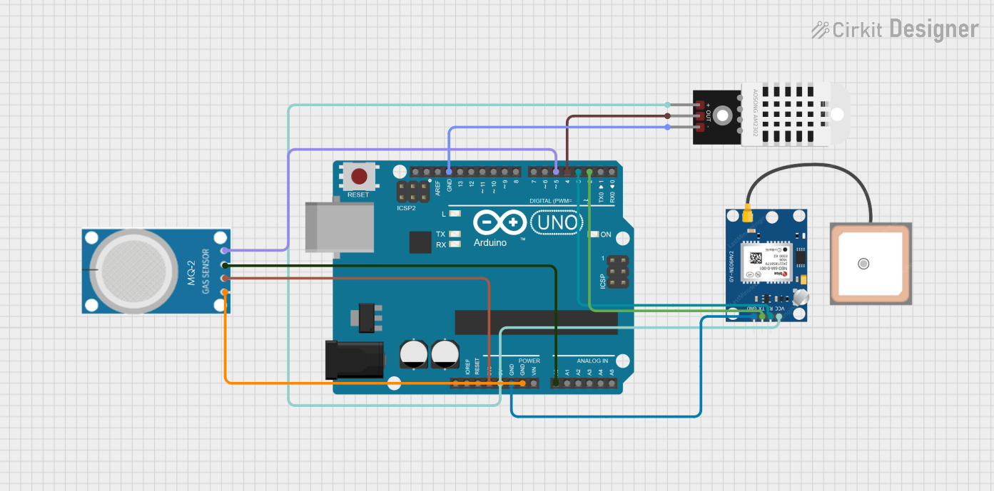
Circuit Documentation
Summary
This circuit integrates an Arduino UNO microcontroller with a GPS NEO 6M module, an MQ-2 gas sensor, and a DHT22 temperature and humidity sensor. The Arduino UNO serves as the central controller, reading data from the sensors and the GPS module, and processing this data for further use.
Component List
Arduino UNO
- Description: A microcontroller board based on the ATmega328P.
- Pins: UNUSED, IOREF, Reset, 3.3V, 5V, GND, Vin, A0, A1, A2, A3, A4, A5, SCL, SDA, AREF, D13, D12, D11, D10, D9, D8, D7, D6, D5, D4, D3, D2, D1, D0
GPS NEO 6M
- Description: A GPS module used for obtaining geographical coordinates.
- Pins: VCC, RX, TX, GND
MQ-2
- Description: A gas sensor used for detecting various gases including LPG, i-butane, propane, methane, alcohol, Hydrogen, and smoke.
- Pins: GND, VCC, ANALOG, Digital
DHT22
- Description: A temperature and humidity sensor.
- Pins: +, Out, -
Wiring Details
Arduino UNO
- 3.3V: Connected to VCC of MQ-2
- 5V: Connected to VCC of GPS NEO 6M and + of DHT22
- GND: Connected to GND of GPS NEO 6M, GND of MQ-2, and - of DHT22
- A0: Connected to ANALOG of MQ-2
- D5: Connected to Digital of MQ-2
- D4: Connected to Out of DHT22
- D3: Connected to RX of GPS NEO 6M
- D2: Connected to TX of GPS NEO 6M
GPS NEO 6M
- VCC: Connected to 5V of Arduino UNO
- GND: Connected to GND of Arduino UNO
- RX: Connected to D3 of Arduino UNO
- TX: Connected to D2 of Arduino UNO
MQ-2
- VCC: Connected to 3.3V of Arduino UNO
- GND: Connected to GND of Arduino UNO
- ANALOG: Connected to A0 of Arduino UNO
- Digital: Connected to D5 of Arduino UNO
DHT22
- +: Connected to 5V of Arduino UNO
- Out: Connected to D4 of Arduino UNO
- -: Connected to GND of Arduino UNO
Code Documentation
Code Overview
The provided code initializes the GPS module and reads data from it. The data is then processed to extract the geographical coordinates, which are displayed on the Serial Monitor.
Code Listing
#include <SoftwareSerial.h>
#include <TinyGPS++.h>

// GPS NEO 6M connections
#define GPS_RX 2
#define GPS_TX 3

SoftwareSerial gpsSerial(GPS_RX, GPS_TX);
TinyGPSPlus gps;

void setup() {
  Serial.begin(9600);  // Start serial communication for debugging
  gpsSerial.begin(9600);  // Start GPS communication

  Serial.println("GPS Test Started...");
}

void loop() {
  // Read data from GPS module
  while (gpsSerial.available()) {
    char c = gpsSerial.read();
    Serial.write(c);  // Print raw GPS data to Serial Monitor

    gps.encode(c);  // Feed data to the TinyGPS++ library

    // If a valid GPS fix is available, display the coordinates
    if (gps.location.isUpdated()) {
      displayGPSData();  // Display current GPS data (lat/lng)
    }
  }

  // Optional: Delay to avoid flooding the serial monitor with too many updates
  delay(1000);
}

void displayGPSData() {
  // Only display if the GPS location is valid
  if (gps.location.isValid()) {
    float latitude = gps.location.lat();
    float longitude = gps.location.lng();
    Serial.print("Latitude: ");
    Serial.print(latitude, 6);  // Print latitude with 6 decimal places
    Serial.print(" Longitude: ");
    Serial.println(longitude, 6);  // Print longitude with 6 decimal places
  } else {
    Serial.println("GPS signal not available.");
  }
}
Code Explanation
Libraries Included:
SoftwareSerial.h: Allows serial communication on other digital pins of the Arduino.TinyGPS++.h: A library for parsing NMEA data from GPS modules.
Pin Definitions:
GPS_RXandGPS_TXare defined for the GPS module's RX and TX pins.
Setup Function:
- Initializes serial communication for debugging and GPS communication.
- Prints a startup message to the Serial Monitor.
Loop Function:
- Continuously reads data from the GPS module.
- Feeds the data to the TinyGPS++ library for parsing.
- If a valid GPS fix is available, it calls
displayGPSData()to print the coordinates.
displayGPSData Function:
- Checks if the GPS location is valid.
- If valid, prints the latitude and longitude to the Serial Monitor.
- If not valid, prints a message indicating that the GPS signal is not available.