
Circuit Documentation
Summary
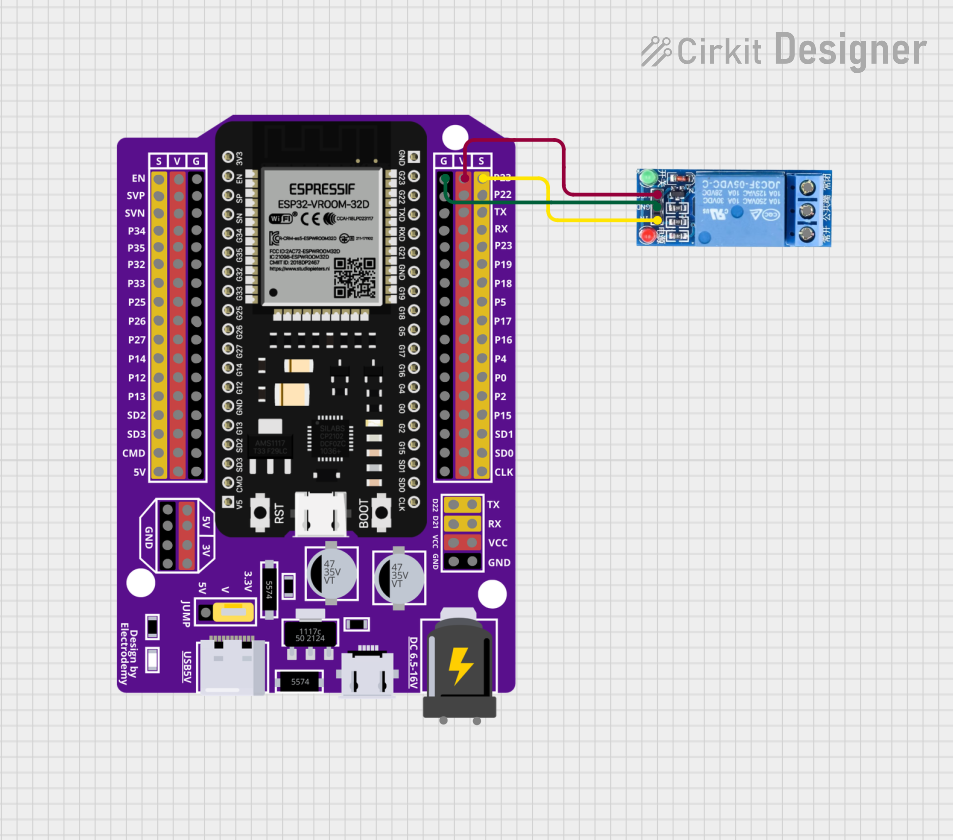
This circuit consists of an ESP32 microcontroller and a 1 Channel Relay module. The ESP32 is used to control the relay, which can be used to switch higher power devices on and off. The relay is connected to the ESP32 through specific pins, and the ESP32 is programmed to toggle the relay state every 5 seconds.
Component List
ESP32 - 38 pins Expansion Board
- Description: A versatile microcontroller with built-in Wi-Fi and Bluetooth capabilities.
- Pins: EN, SVP, SVN, P34, P35, P32, P33, P25, P26, P27, P14, P12, P13, SD2, SD3, CMD, 5V, P23, P22, TX, RX, P19, P18, P5, P17, P16, P4, P0, P2, P15, SD1, SD0, CLK, VCC, G, D22, D21, 3V, V, +, -
1 Channel Relay 5V
- Description: A relay module that allows a microcontroller to control a high-power device.
- Pins: VCC, GND, IN, NC, COM, NO
Wiring Details
ESP32 - 38 pins Expansion Board
- P23 is connected to IN of the 1 Channel Relay 5V.
- V is connected to VCC of the 1 Channel Relay 5V.
- G is connected to GND of the 1 Channel Relay 5V.
1 Channel Relay 5V
- IN is connected to P23 of the ESP32.
- VCC is connected to V of the ESP32.
- GND is connected to G of the ESP32.
Code Documentation
ESP32 - 38 pins Expansion Board
#include <Arduino.h>

// Relay Pin
#define RELAY_PIN 23 // Pin untuk mengontrol relay

void setup() {
    Serial.begin(115200);

    // Konfigurasi pin relay sebagai output
    pinMode(RELAY_PIN, OUTPUT);
    digitalWrite(RELAY_PIN, LOW); // Relay mati secara default
}

void loop() {
    // Nyalakan relay
    digitalWrite(RELAY_PIN, HIGH);
    Serial.println("Relay ON");

    // Tunggu selama 5 detik
    delay(5000);

    // Matikan relay
    digitalWrite(RELAY_PIN, LOW);
    Serial.println("Relay OFF");

    // Tunggu selama 5 detik
    delay(5000);
}
1 Channel Relay 5V
void setup() {
  // put your setup code here, to run once:

}

void loop() {
  // put your main code here, to run repeatedly:

}
This documentation provides a comprehensive overview of the circuit, including a summary, detailed component list, wiring details, and the code used to control the relay via the ESP32 microcontroller.