
Arduino UNO-Based Smart Water Monitoring System with GPS and Rain Detection
View and Edit Project In Cirkit Designer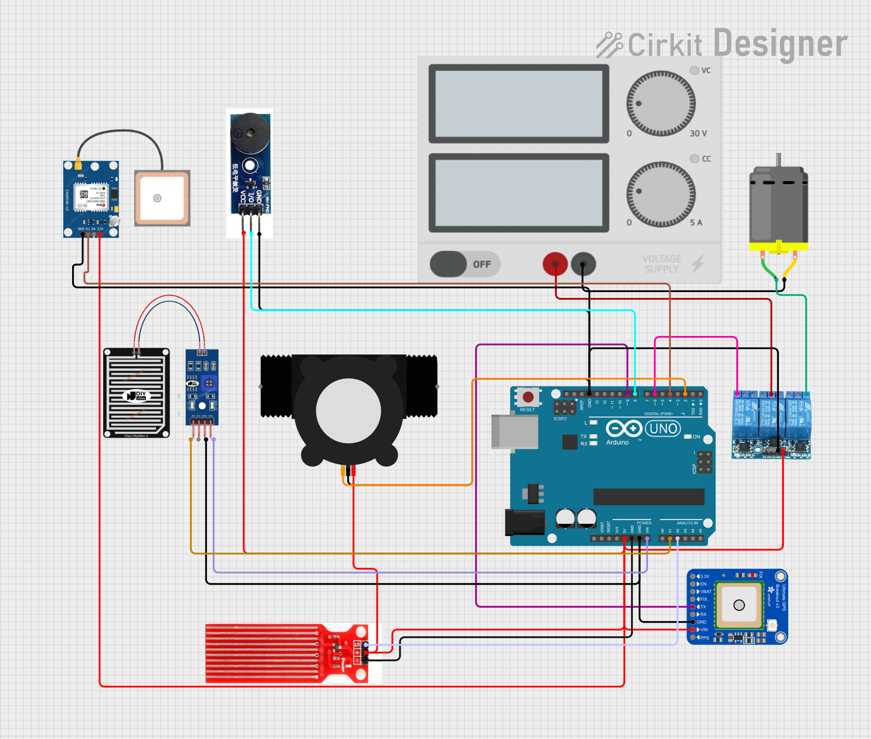
Circuit Documentation
Summary
This circuit is designed to monitor water flow, detect rain, and measure water levels. It uses an Arduino UNO as the central microcontroller to interface with various sensors and modules, including a water flow sensor, a rain sensor, a water level sensor, a GPS module, a relay, a DC motor, and a buzzer. The circuit also includes a power supply to provide the necessary voltage to the components.
Component List
Arduino UNO
- Description: Microcontroller board based on the ATmega328P.
- Pins: UNUSED, IOREF, Reset, 3.3V, 5V, GND, Vin, A0, A1, A2, A3, A4, A5, SCL, SDA, AREF, D13, D12, D11, D10, D9, D8, D7, D6, D5, D4, D3, D2, D1, D0
Water Sensor
- Description: Sensor to detect water presence.
- Pins: Signal, VCC, GND
Adafruit Ultimate GPS v3
- Description: GPS module for location tracking.
- Pins: 1PPS, VIN, GND, RX, TX, FIX, VBACKUP, ENABLE, 3.3V
YF-S201 Water Flow Meter
- Description: Sensor to measure water flow rate.
- Pins: SIG, GND, VCC
3 Channel Relay 5V
- Description: Relay module to control high voltage devices.
- Pins: COMMON, NO, NC, VCC, GND, CH3, CH2, CH1
Power Supply
- Description: Provides power to the circuit.
- Pins: +, -
DC Motor
- Description: Motor for mechanical movement.
- Pins: pin 1, pin 2
Active Buzzer Module
- Description: Buzzer for audio alerts.
- Pins: GND, I/O, VCC
RAIN SENSOR
- Description: Sensor to detect rain.
- Pins: AO, DO, GRD, VCC
GPS NEO 6M
- Description: GPS module for location tracking.
- Pins: VCC, RX, TX, GND
Wiring Details
Arduino UNO
5V connected to:
- 3 Channel Relay 5V (VCC)
- GPS NEO 6M (VCC)
- YF-S201 Water Flow Meter (VCC)
- Adafruit Ultimate GPS v3 (VIN)
- Water Sensor (VCC)
- Active Buzzer Module (VCC)
GND connected to:
- Water Sensor (GND)
- Adafruit Ultimate GPS v3 (GND)
- RAIN SENSOR (GRD)
- 3 Channel Relay 5V (GND)
- GPS NEO 6M (GND)
- YF-S201 Water Flow Meter (GND)
- Active Buzzer Module (GND)
Vin connected to:
- RAIN SENSOR (VCC)
A1 connected to:
- RAIN SENSOR (AO)
A2 connected to:
- Water Sensor (Signal)
D9 connected to:
- Adafruit Ultimate GPS v3 (TX)
D8 connected to:
- Active Buzzer Module (I/O)
D6 connected to:
- 3 Channel Relay 5V (NC)
D4 connected to:
- GPS NEO 6M (TX)
D2 connected to:
- YF-S201 Water Flow Meter (SIG)
3 Channel Relay 5V
COMMON connected to:
- Power Supply (+)
NO connected to:
- DC Motor (pin 1)
GND connected to:
- GPS NEO 6M (GND)
- YF-S201 Water Flow Meter (GND)
- Arduino UNO (GND)
- Active Buzzer Module (GND)
DC Motor
- pin 2 connected to:
- Power Supply (-)
Code Documentation
Arduino UNO Code
// Water Flow Sensor
const int flowSensorPin = 2;  // Digital pin for flow sensor
volatile int flowPulseCount = 0; // Pulse count for flow sensor
float flowRate = 0.0; // Flow rate in liters per minute
unsigned long previousMillis = 0;
float calibrationFactor = 7.5; // Calibration factor for YF-S402B
unsigned long interval = 1000; // 1 second interval

// Raindrop Sensor
const int rainSensorPin = A1; // Analog pin for raindrop sensor
int rainSensorValue = 0;

// Water Level Sensor
const int waterLevelPin = A2; // Analog pin for water level sensor
const int buzzerPin = 8;      // Digital pin for buzzer
const int waterLevelThreshold = 500; // Water level threshold for triggering the buzzer

void setup() {
  // Start serial communication
  Serial.begin(9600);

  // Setup pins
  pinMode(flowSensorPin, INPUT);
  pinMode(buzzerPin, OUTPUT);

  // Attach interrupt for flow sensor
  attachInterrupt(digitalPinToInterrupt(flowSensorPin), countFlowPulse, FALLING);
}

void loop() {
  unsigned long currentMillis = millis();

  // Flow Sensor: Calculate and display flow rate every second
  if (currentMillis - previousMillis >= interval) {
    float liters = flowPulseCount / calibrationFactor;  // Convert pulses to liters
    flowRate = liters * 60.0;  // Convert to liters per minute
    Serial.print("Flow Rate: ");
    Serial.print(flowRate);
    Serial.println(" L/min");

    // Reset pulse count and update last time
    flowPulseCount = 0;
    previousMillis = currentMillis;
  }

  // Raindrop Sensor: Read raindrop sensor value and display
  rainSensorValue = analogRead(rainSensorPin);
  Serial.print("Raindrop Sensor Value: ");
  Serial.println(rainSensorValue);
  if (rainSensorValue < 500) {
    Serial.println("Raindrop detected!");
  } else {
    Serial.println("No rain detected.");
  }

  // Water Level Sensor: Check water level and activate buzzer
  int waterLevel = analogRead(waterLevelPin);
  Serial.print("Water Level: ");
  Serial.println(waterLevel);
  if (waterLevel > waterLevelThreshold) {
    digitalWrite(buzzerPin, HIGH);  // Turn buzzer on
    Serial.println("Water level high! Buzzer ON");
  } else {
    digitalWrite(buzzerPin, LOW);   // Turn buzzer off
    Serial.println("Water level normal. Buzzer OFF");
  }

  delay(500); // Delay for stability in serial output
}

// Interrupt function to count pulses for flow sensor
void countFlowPulse() {
  flowPulseCount++;  // Increment pulse count for each pulse
}
This code is designed to interface with the water flow sensor, raindrop sensor, and water level sensor. It reads the sensor values, calculates the flow rate, and triggers a buzzer if the water level exceeds a certain threshold. The code also includes serial communication to display the sensor readings and status messages.