Cirkit Designer
Your all-in-one circuit design IDE
Home /
Project Documentation
Arduino-Controlled Robotics Platform with Ultrasonic and IR Sensing

Circuit Documentation
Summary
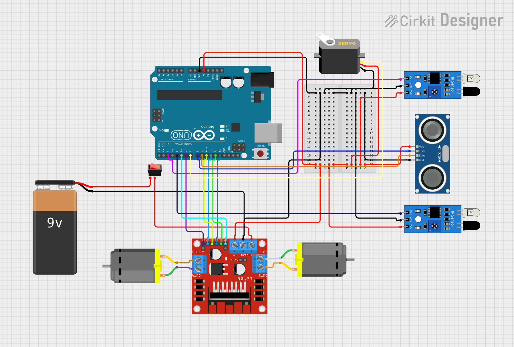
This circuit is designed to interface an Arduino UNO with various sensors and actuators, including ultrasonic sensors (HC-SR04), infrared sensors, a servo motor, DC motors, and a motor driver (L298N). The circuit is powered by a 9V battery, which is controlled by a rocker switch. The Arduino UNO is used as the central processing unit, reading sensor inputs and controlling the actuators based on the programmed logic.
Component List
HC-SR04 Ultrasonic Sensor
- Pins: VCC, TRIG, ECHO, GND
- Description: This sensor is used to measure distance by emitting ultrasonic waves and measuring the time taken for the echo to return.
Arduino UNO
- Pins: UNUSED, IOREF, Reset, 3.3V, 5V, GND, Vin, A0-A5, SCL, SDA, AREF, D0-D13
- Description: The Arduino UNO is a microcontroller board based on the ATmega328P. It is the main controller used to process inputs and outputs in the circuit.
IR Sensor
- Pins: out, gnd, vcc
- Description: Infrared sensors are used to detect obstacles or measure distances using infrared light.
Rocker Switch
- Pins: output, input
- Description: A rocker switch is used to control the power supply to the circuit.
9V Battery
- Pins: -, +
- Description: Provides the power source for the circuit.
DC Motor
- Pins: pin 1, pin 2
- Description: Electric motors that convert electrical energy into mechanical motion.
L298N DC Motor Driver
- Pins: OUT1, OUT2, 12V, GND, 5V, OUT3, OUT4, 5V-ENA-JMP-I, 5V-ENA-JMP-O, +5V-J1, +5V-J2, ENA, IN1, IN2, IN3, IN4, ENB
- Description: A motor driver module that allows for control of the speed and direction of two DC motors.
Servo
- Pins: gnd, vcc, pulse
- Description: A rotary actuator or linear actuator that allows for precise control of angular or linear position.
Wiring Details
HC-SR04 Ultrasonic Sensor
- VCC: Connected to 5V power supply.
- TRIG: Connected to Arduino UNO pin D8.
- ECHO: Connected to Arduino UNO pin D9.
- GND: Connected to the common ground.
Arduino UNO
- 5V: Provides power to the HC-SR04 Ultrasonic Sensor, IR sensors, and L298N motor driver.
- GND: Common ground for all components.
- D8: Connected to HC-SR04 TRIG pin.
- D9: Connected to HC-SR04 ECHO pin.
- D4, D2: Connected to IR sensor output pins.
- D5, D6: Connected to L298N motor driver ENA and ENB pins for enabling motor control.
- D7: Connected to Servo pulse pin.
- D10-D13: Connected to L298N motor driver IN1-IN4 pins for motor direction control.
IR Sensor
- out: Connected to Arduino UNO pins D4 and D2 for two IR sensors.
- gnd: Connected to the common ground.
- vcc: Connected to 5V power supply.
Rocker Switch
- input: Connected to the positive terminal of the 9V Battery.
- output: Connected to the 12V input of the L298N motor driver.
9V Battery
- -: Connected to the common ground.
- +: Connected to the input of the rocker switch.
DC Motor
- pin 1, pin 2: Connected to L298N motor driver OUT1, OUT2 for one motor and OUT3, OUT4 for the other motor.
L298N DC Motor Driver
- OUT1, OUT2, OUT3, OUT4: Connected to DC motor pins.
- 12V: Connected to the output of the rocker switch.
- GND: Connected to the common ground.
- 5V: Connected to 5V power supply.
- ENA, ENB: Connected to Arduino UNO pins D5 and D6 for enabling motor control.
- IN1-IN4: Connected to Arduino UNO pins D10-D13 for motor direction control.
Servo
- gnd: Connected to the common ground.
- vcc: Connected to 5V power supply.
- pulse: Connected to Arduino UNO pin D7.
Documented Code
// Arduino UNO Code for the Circuit
// Filename: sketch.ino

// Define pin connections & motor speed variables
const int trigPin = 8;
const int echoPin = 9;
const int irSensor1 = 4;
const int irSensor2 = 2;
const int motorPin1 = 12;
const int motorPin2 = 13;
const int motorPin3 = 11;
const int motorPin4 = 10;
const int servoPin = 7;
const int motorSpeed = 255; // Max speed

// Setup function runs once at the start of the program
void setup() {
  // Initialize all the motor control pins as outputs
  pinMode(motorPin1, OUTPUT);
  pinMode(motorPin2, OUTPUT);
  pinMode(motorPin3, OUTPUT);
  pinMode(motorPin4, OUTPUT);

  // Initialize the servo control pin as an output
  pinMode(servoPin, OUTPUT);

  // Initialize the IR sensor pins as inputs
  pinMode(irSensor1, INPUT);
  pinMode(irSensor2, INPUT);

  // Initialize the ultrasonic sensor pins
  pinMode(trigPin, OUTPUT);
  pinMode(echoPin, INPUT);

  // Begin serial communication at a baud rate of 9600
  Serial.begin(9600);
}

// Loop function runs repeatedly after setup function
void loop() {
  // Implement sensor reading and motor control logic here
  // ...
}
Please note that the provided code is a template and does not contain the actual logic for reading sensors or controlling motors. The user should implement the specific logic based on the requirements of their application.