
Arduino UNO Mini Centrifuge with LCD RPM Display and BLDC Motor Control
View and Edit Project In Cirkit Designer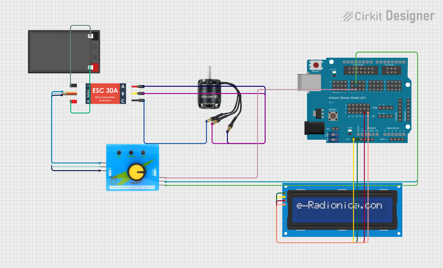
Circuit Documentation
Summary
This project is a Mini Centrifuge that utilizes an Arduino UNO with a Sensor Shield v5.0 to control a BLDC motor via a servo tester and an Electronic Speed Controller (ESC). The RPM of the motor is displayed on an LCD 16x2 I2C screen. The system is powered by a 12V 7Ah battery.
Component List
Arduino UNO
- Description: Microcontroller board based on the ATmega328P.
- Pins: UNUSED, IOREF, Reset, 3.3V, 5V, GND, Vin, A0, A1, A2, A3, A4, A5, SCL, SDA, AREF, D13, D12, D11, D10, D9, D8, D7, D6, D5, D4, D3, D2, D1, D0
Arduino Sensor Shield v5.0
- Description: Expansion shield for Arduino UNO to easily connect sensors and actuators.
- Pins: VCC, SD-VCC, SD-GND, SD-D11, SD-D10, SD-D13, SD-D12, URF01-VCC, URF01-A0, URF01-A1, URF01-GND, GND, SEL1, SEL2, A0-SIG, A0-VCC, A0-GND, A1-SIG, A1-VCC, A1-GND, A2-SIG, A2-VCC, A2-GND, A3-SIG, A3-VCC, A3-GND, A4-SIG, A4-VCC, A4-GND, A5-SIG, A5-VCC, A5-GND, IIC-SCL, IIC-SDA, IIC-GND, IIC-VCC, COM-TX, COM-RX, COM-GND, COM-VCC, APC220-, APC220-D0, APC220-D1, APC220-VCC, APC220-GND, BLUETOOTH-3V3, BLUETOOTH-GND, BLUETOOTH-D0, BLUETOOTH-D1, BLUETOOTH-VCC, AREF-S, AREF-V, AREF-G, GND-S, GND-V, GND-G, 13-S, 13-V, 13-G, 12-S, 12-V, 12-G, 11-S, 11-V, 11-G, 10-S, 10-V, 10-G, 9-S, 9-V, 9-G, 8-S, 8-V, 8-G, 7-S, 7-V, 7-G, 6-S, 6-V, 6-G, 5-S, 5-V, 5-G, 4-S, 4-V, 4-G, 3-S, 3-V, 3-G, 2-S, 2-V, 2-G, 1-S, 1-V, 1-G, 0-S, 0-V, 0-G, ParallelLCD-VCC, ParallelLCD-D13, ParallelLCD-GND, ParallelLCD-D12, ParallelLCD-D2, ParallelLCD-D11, ParallelLCD-D3, ParallelLCD-D10, ParallelLCD-D4, ParallelLCD-D9, ParallelLCD-D5, ParallelLCD-D8, ParallelLCD-D6, ParallelLCD-D7, SerialLCD-D4, SerialLCD-VCC, SerialLCD-D3, SerialLCD-, SerialLCD-D2, SerialLCD-GND
Electronic Speed Controller (ESC)
- Description: Device to control the speed of a BLDC motor.
- Pins: Battery VCC, Battery GND, Signal, 5v out, GND out, M1, M2, M3
BLDC Motor
- Description: Brushless DC motor.
- Pins: Wire A, Wire B, Wire C
LCD screen 16x2 I2C
- Description: 16x2 character LCD with I2C interface.
- Pins: SCL, SDA, VCC, GND
Servo Tester
- Description: Device to test and control servo motors.
- Pins: GND, 5V, S, VCC
12V 7Ah Battery
- Description: Power source for the circuit.
- Pins: 12v +, 12v -
Wiring Details
Arduino Sensor Shield v5.0
- SD-VCC connected to LCD screen 16x2 I2C VCC
- SD-GND connected to LCD screen 16x2 I2C GND
- A4-SIG connected to LCD screen 16x2 I2C SDA
- A5-SIG connected to LCD screen 16x2 I2C SCL
- 10-S connected to Servo Tester S
- 10-V connected to Servo Tester 5V
- 10-G connected to Servo Tester GND
Electronic Speed Controller (ESC)
- Battery VCC connected to 12V 7Ah Battery 12v +
- Battery GND connected to 12V 7Ah Battery 12v -
- Signal connected to Servo Tester S
- 5v out connected to Servo Tester VCC
- GND out connected to Servo Tester GND
- M1 connected to BLDC Motor Wire A
- M2 connected to BLDC Motor Wire B
- M3 connected to BLDC Motor Wire C
Code Documentation
/*
 * Mini Centrifuge Project
 * Components:
 * - Arduino UNO with Sensor Shield v5.0
 * - Servo Tester for speed control of 12V BLDC
 * - 30A ESC
 * - LCD 16x2 I2C for RPM display
 *
 * This code controls a BLDC motor using a servo tester and ESC. The RPM is
 * displayed on an LCD 16x2 I2C screen.
 */

#include <Wire.h>
#include <LiquidCrystal_I2C.h>

// LCD I2C address and dimensions
LiquidCrystal_I2C lcd(0x27, 16, 2);

// Pin definitions
const int servoTesterSignalPin = 10; // Connected to Servo Tester S pin

void setup() {
  // Initialize the LCD
  lcd.begin();
  lcd.backlight();
  lcd.setCursor(0, 0);
  lcd.print("Mini Centrifuge");
  delay(2000);
  lcd.clear();

  // Initialize the servo tester signal pin
  pinMode(servoTesterSignalPin, OUTPUT);
}

void loop() {
  // Example: Set motor speed and display RPM
  int motorSpeed = 1500; // Example speed value
  analogWrite(servoTesterSignalPin, motorSpeed);

  // Calculate RPM (example calculation)
  int rpm = map(motorSpeed, 0, 255, 0, 10000);

  // Display RPM on LCD
  lcd.setCursor(0, 0);
  lcd.print("RPM: ");
  lcd.print(rpm);

  delay(1000); // Update every second
}
This code initializes the LCD and sets up the servo tester signal pin. In the loop, it sets the motor speed and calculates the RPM, which is then displayed on the LCD. The RPM is updated every second.