
ESP32-Based Smart Weather Station with Light Sensing and Humidity Alert
View and Edit Project In Cirkit Designer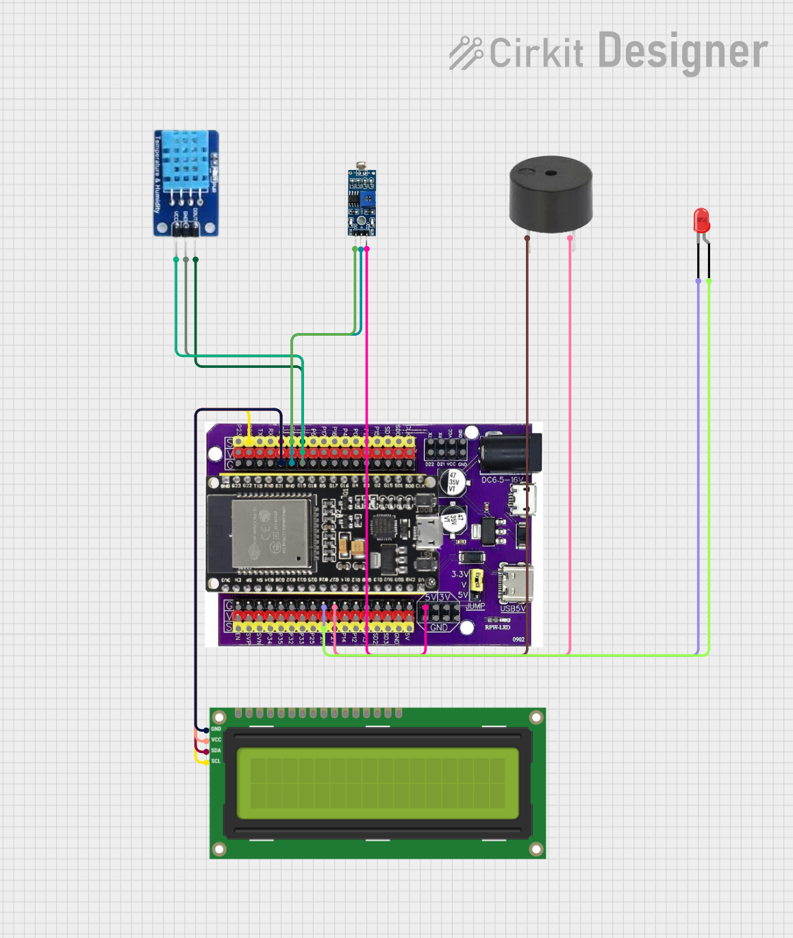
Circuit Documentation
Summary
This circuit is designed to function as a weather station, featuring an ESP32 microcontroller as the central processing unit. It includes an LDR (Light Dependent Resistor) module for light sensing, a DHT11 sensor for measuring temperature and humidity, a buzzer for audible alerts, an LED for visual indication, and an I2C LCD 16x2 screen for displaying sensor data. The ESP32 microcontroller is responsible for reading sensor data, controlling the output devices (buzzer and LED), and displaying the information on the LCD screen.
Component List
LDR Module 3 pin
- Description: A light sensor module that outputs a digital signal.
- Pins: VCC, GND, DO
Buzzer
- Description: An audible signaling device.
- Pins: PIN, GND
LED: Two Pin (red)
- Description: A red light-emitting diode for visual indication.
- Pins: Cathode, Anode
I2C LCD 16x2 Screen
- Description: A 16x2 character LCD display with an I2C interface.
- Pins: SCL, SDA, VCC (5V), GND, VDD, VO, RS, RW, E, D0, D1, D2, D3, D4, D5, D6, D7, BLA, BLK
Esp32 on Baseboard
- Description: A powerful microcontroller with Wi-Fi and Bluetooth capabilities.
- Pins: Multiple GPIOs, power, and communication pins.
DHT11
- Description: A basic, ultra-low-cost digital temperature and humidity sensor.
- Pins: DATA, GND, VCC
Wiring Details
LDR Module 3 pin
- VCC connected to Esp32 5V
- GND connected to Esp32 GND
- DO connected to Esp32 GPIO19
Buzzer
- PIN connected to Esp32 GPIO27
- GND connected to Esp32 GND
LED: Two Pin (red)
- Anode connected to Esp32 GPIO26
- Cathode connected to Esp32 GND
I2C LCD 16x2 Screen
- SCL connected to Esp32 GPIO22
- SDA connected to Esp32 GPIO21
- VCC (5V) connected to Esp32 V
- GND connected to Esp32 GND
DHT11
- DATA connected to Esp32 GPIO18
- GND connected to Esp32 GND
- VCC connected to Esp32 V
Documented Code
#include <DHT.h>
#include <LiquidCrystal_I2C.h>

// DHT sensor configuration
#define DHT11_PIN   18 // ESP32 pin GPIO18 connected to DHT11 sensor
#define BUZZER_PIN  27 // GPIO pin for buzzer
#define LED_PIN     26 // GPIO pin for LED
#define LIGHT_SENSOR_PIN 19 // GPIO pin for LDR sensor
#define HMDT_THRESHOLD 67.0 // Humidity threshold

// Initialize DHT11 sensor and LCD display
DHT dht11(DHT11_PIN, DHT11);
LiquidCrystal_I2C lcd(0x27, 16, 2); // I2C address, 16 columns, 2 rows

void setup() {
  Serial.begin(9600);

  // Initialize DHT11 and LCD
  dht11.begin();
  lcd.init();
  lcd.backlight();

  // Initialize pin modes
  pinMode(BUZZER_PIN, OUTPUT);
  pinMode(LED_PIN, OUTPUT);
  pinMode(LIGHT_SENSOR_PIN, INPUT);

  digitalWrite(BUZZER_PIN, LOW); // Ensure buzzer is off
  digitalWrite(LED_PIN, LOW); // Ensure LED is off
}

void loop() {
  // Read humidity and temperature
  float humi  = dht11.readHumidity();
  float tempC = dht11.readTemperature();
  float tempF = dht11.readTemperature(true);

  // Read light sensor value
  int digitalValue = digitalRead(LIGHT_SENSOR_PIN);
  String lightStatus = (digitalValue == LOW) ? "Bright" : "Dark";
  if (digitalValue == HIGH) {
    Serial.println(" => Bright");
    Serial.println();
    digitalWrite(LED_PIN, HIGH); // Turn off LED if bright
  } else {
    Serial.println(" => Dark");
    Serial.println();
    digitalWrite(LED_PIN, LOW); // Turn on LED if dark
  }

  // Check if the readings are valid
  if (isnan(tempC) || isnan(tempF) || isnan(humi)) {
    Serial.println("Failed to read from DHT11 sensor!");
    lcd.clear();
    lcd.setCursor(0, 0);
    lcd.print("Sensor Error!");
  } else {
    // Display data on Serial Monitor
    Serial.print("Humidity: ");
    Serial.print(humi);
    Serial.print("% | Temp: ");
    Serial.print(tempC);
    Serial.print("C / ");
    Serial.print(tempF);
    Serial.print("F | Light: ");
    Serial.println(lightStatus);

    // Display data on LCD
    lcd.clear();
    lcd.setCursor(0, 0);
    lcd.print("H:");
    lcd.print(humi);
    lcd.print("% T:");
    lcd.print(tempC);
    lcd.print("C");

    lcd.setCursor(0, 1);
    lcd.print("L:");
    lcd.print(lightStatus);
    lcd.print(" F:");
    lcd.print(tempF);
    lcd.print("F");

    // Check humidity for alert
    if (humi < HMDT_THRESHOLD) {
      digitalWrite(BUZZER_PIN, HIGH); // Activate buzzer
      digitalWrite(LED_PIN, HIGH); // Turn on LED

      // Override LCD display with alert
      lcd.clear();
      lcd.setCursor(0, 0);
      lcd.print("Alert! Low Humid!");
      lcd.setCursor(0, 1);
      lcd.print("H:");
      lcd.print(humi);
      lcd.print("% - Air Dry!");

      Serial.println("Alert! Air Too Dry!");
    } else {
      digitalWrite(BUZZER_PIN, LOW); // Deactivate buzzer
      digitalWrite(LED_PIN, LOW); // Turn off LED
    }
  }

  // Wait 500ms seconds between readings
  delay(500);
}
This code is designed to run on the ESP32 microcontroller. It initializes the DHT11 sensor and the I2C LCD display, reads temperature, humidity, and light sensor data, and displays the information on the LCD screen. It also controls the buzzer and LED based on the humidity level and light sensor input.