
ESP32-Based Wi-Fi Controlled LCD Display with Pushbutton Interface
View and Edit Project In Cirkit Designer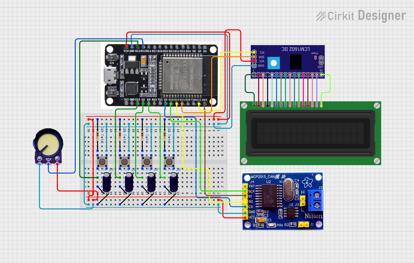
Circuit Documentation
Summary
This circuit involves an ESP32 microcontroller interfacing with various components including an LCD Display, an LCM1602 IIC module, a potentiometer, pushbuttons, resistors, electrolytic capacitors, and an MCP2515 CAN controller. The ESP32 serves as the central control unit, managing inputs from pushbuttons and a potentiometer, and displaying information on an LCD screen via the LCM1602 IIC module. The MCP2515 CAN controller is used for CAN bus communication.
Component List
LCD Display (16 pin)
- Description: A 16-pin LCD display used for visual output.
- Pins: VSS, VDD, VO, RS, R_W, E, DB0, DB1, DB2, DB3, DB4, DB5, DB6, DB7, A, K
ESP32
- Description: A powerful microcontroller with Wi-Fi and Bluetooth capabilities.
- Pins: EN, VP, VN, D34, D35, D32, D33, D25, D26, D27, D14, D12, D13, GND, VIN, 3V3, D15, D2, D4, RX2, TX2, D5, D18, D19, D21, RX0, TX0, D22, D23, BOOT
LCM1602 IIC
- Description: An I2C interface module for the LCD display.
- Pins: GND, VCC, SDA, SCL, D6, D7, A, K, VSS, VDD, V0, RS, D2, D3, D4, D5, RW, E, D0, D1, LED_A, LED_B
Potentiometer
- Description: A variable resistor used to adjust voltage levels.
- Pins: GND, Output, VCC
Pushbutton
- Description: A simple pushbutton switch.
- Pins: Pin 3 (out), Pin 4 (out), Pin 1 (in), Pin 2 (in)
Resistor
- Description: A 10k Ohm resistor.
- Pins: pin1, pin2
- Properties: Resistance: 10k Ohms
Electrolytic Capacitor
- Description: A 4.7µF electrolytic capacitor.
- Pins: -, +
- Properties: Capacitance: 4.7µF
MCP2515
- Description: A CAN controller module.
- Pins: INT, SCK, SI, SO, CS, GND, VCC, H, L
Wiring Details
LCD Display (16 pin)
- VSS connected to VSS of LCM1602 IIC
- VDD connected to VDD of LCM1602 IIC
- VO connected to V0 of LCM1602 IIC
- RS connected to RS of LCM1602 IIC
- R_W connected to RW of LCM1602 IIC
- E connected to E of LCM1602 IIC
- DB0 connected to D0 of LCM1602 IIC
- DB1 connected to D1 of LCM1602 IIC
- DB2 connected to D2 of LCM1602 IIC
- DB3 connected to D3 of LCM1602 IIC
- DB4 connected to D4 of LCM1602 IIC
- DB5 connected to D5 of LCM1602 IIC
- DB6 connected to D6 of LCM1602 IIC
- DB7 connected to D7 of LCM1602 IIC
- A connected to A of LCM1602 IIC
- K connected to K of LCM1602 IIC
ESP32
- GND connected to:
- Pin 3 (out) of all Pushbuttons
- GND of LCM1602 IIC
- + of all Electrolytic Capacitors
- GND of MCP2515
- GND of Potentiometer
- D4 connected to Pin 2 (in) of Pushbutton and - of Electrolytic Capacitor
- D2 connected to Pin 2 (in) of Pushbutton and - of Electrolytic Capacitor
- D15 connected to Pin 2 (in) of Pushbutton and - of Electrolytic Capacitor
- D13 connected to Pin 2 (in) of Pushbutton and - of Electrolytic Capacitor
- VIN connected to:
- pin1 of all Resistors
- VCC of LCM1602 IIC
- VCC of MCP2515
- VCC of Potentiometer
- D12 connected to Output of Potentiometer
- D5 connected to CS of MCP2515
- D18 connected to SCK of MCP2515
- D19 connected to SO of MCP2515
- D21 connected to SDA of LCM1602 IIC
- D22 connected to SCL of LCM1602 IIC
- D23 connected to SI of MCP2515
LCM1602 IIC
- GND connected to GND of ESP32
- VCC connected to VIN of ESP32
- SDA connected to D21 of ESP32
- SCL connected to D22 of ESP32
- VSS connected to VSS of LCD Display
- VDD connected to VDD of LCD Display
- V0 connected to VO of LCD Display
- RS connected to RS of LCD Display
- RW connected to R_W of LCD Display
- E connected to E of LCD Display
- D0 connected to DB0 of LCD Display
- D1 connected to DB1 of LCD Display
- D2 connected to DB2 of LCD Display
- D3 connected to DB3 of LCD Display
- D4 connected to DB4 of LCD Display
- D5 connected to DB5 of LCD Display
- D6 connected to DB6 of LCD Display
- D7 connected to DB7 of LCD Display
- A connected to A of LCD Display
- K connected to K of LCD Display
Potentiometer
- GND connected to GND of ESP32
- Output connected to D12 of ESP32
- VCC connected to VIN of ESP32
Pushbutton
- Pin 3 (out) connected to GND of ESP32
- Pin 2 (in) connected to:
- D4 of ESP32 and - of Electrolytic Capacitor
- D2 of ESP32 and - of Electrolytic Capacitor
- D15 of ESP32 and - of Electrolytic Capacitor
- D13 of ESP32 and - of Electrolytic Capacitor
- Pin 1 (in) connected to pin2 of Resistor
Resistor
- pin1 connected to VIN of ESP32
- pin2 connected to Pin 1 (in) of Pushbutton
Electrolytic Capacitor
- + connected to GND of ESP32
- - connected to:
- D4 of ESP32 and Pin 2 (in) of Pushbutton
- D2 of ESP32 and Pin 2 (in) of Pushbutton
- D15 of ESP32 and Pin 2 (in) of Pushbutton
- D13 of ESP32 and Pin 2 (in) of Pushbutton
MCP2515
- GND connected to GND of ESP32
- VCC connected to VIN of ESP32
- CS connected to D5 of ESP32
- SCK connected to D18 of ESP32
- SO connected to D19 of ESP32
- SI connected to D23 of ESP32
Code
No code provided.