Cirkit Designer
Your all-in-one circuit design IDE
Home /
Project Documentation
Arduino UNO Based RFID Access Control with Servomotor Actuation and Ultrasonic Sensing

Circuit Documentation
Summary of the Circuit
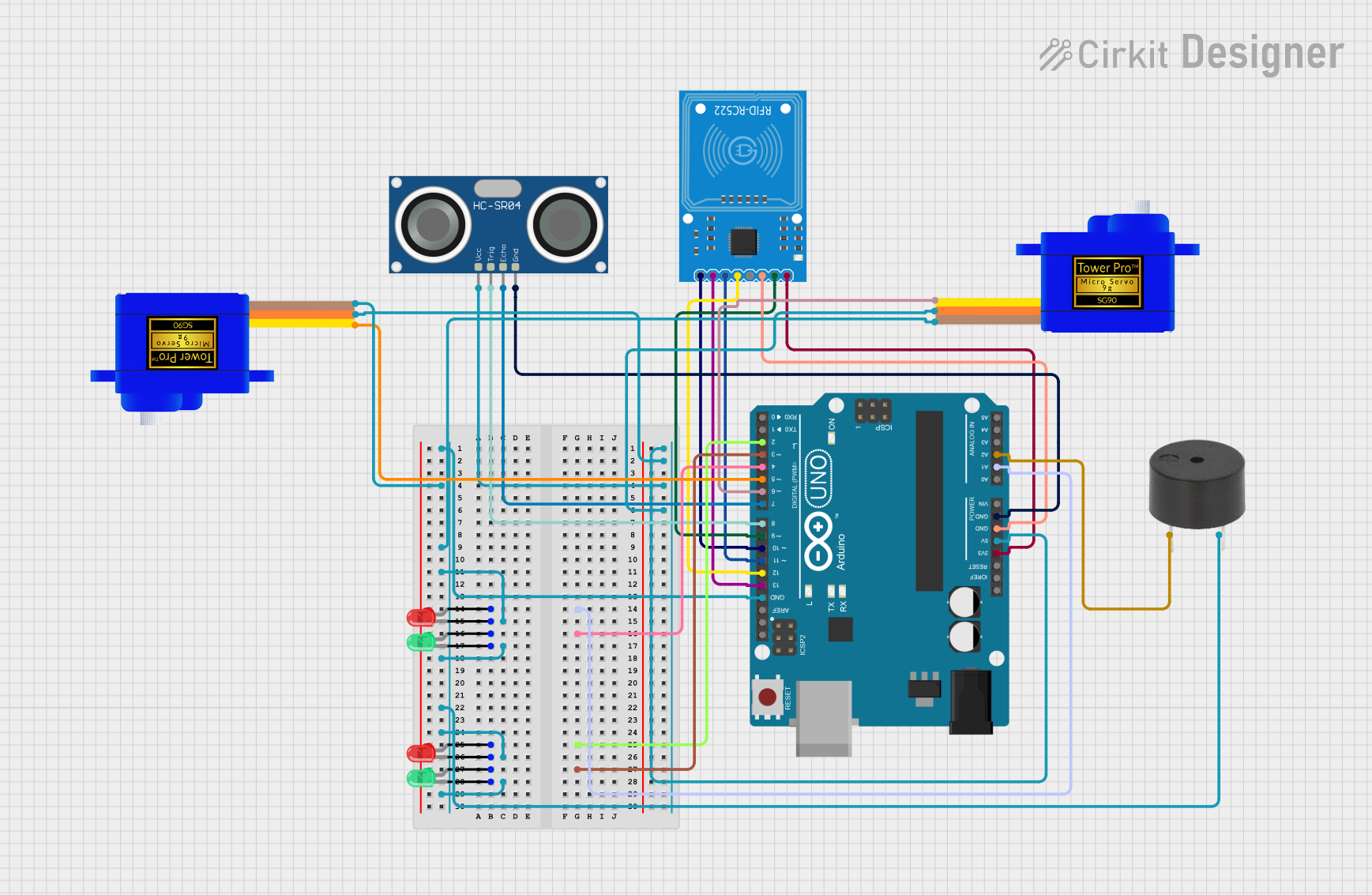
This circuit is designed around an Arduino UNO microcontroller, which serves as the central processing unit for controlling various peripherals including servomotors, LEDs, a buzzer, an HC-SR04 ultrasonic sensor, and an RFID-RC522 module. The circuit appears to be a multifunctional system capable of interacting with the environment through the ultrasonic sensor, providing visual indicators via LEDs, moving parts with servomotors, reading RFID tags, and giving audio feedback with a buzzer.
Component List
Servomotor SG90
- Description: A small and lightweight servo used for precise control of motion.
- Pins: SIG (Signal), VCC (Power), GND (Ground)
LED: Two Pin (green)
- Description: A green light-emitting diode used as an indicator light.
- Pins: cathode (Negative), anode (Positive)
LED: Two Pin (red)
- Description: A red light-emitting diode used as an indicator light.
- Pins: cathode (Negative), anode (Positive)
HC-SR04 Ultrasonic Sensor
- Description: A sensor that measures distance by emitting ultrasonic waves and measuring the time taken for the echo to return.
- Pins: VCC (Power), TRIG (Trigger), ECHO (Echo), GND (Ground)
RFID-RC522
- Description: An RFID reader/writer module for contactless communication using radio frequency.
- Pins: SDA (Serial Data), SCK (Serial Clock), MOSI (Master Out Slave In), MISO (Master In Slave Out), IRQ (Interrupt Request), GND (Ground), RST (Reset), 3.3V (Power)
Arduino UNO
- Description: A microcontroller board based on the ATmega328P, widely used for building digital devices and interactive objects.
- Pins: Various digital and analog I/O pins, power supply pins, and communication interfaces.
Buzzer
- Description: An audio signaling device that can be used to create beeps or alerts.
- Pins: PIN (Signal), GND (Ground)
Wiring Details
Servomotor SG90
- Signal: Connected to Arduino UNO digital pins (D5, D6)
- Power (VCC): Connected to Arduino UNO 5V
- Ground (GND): Connected to Arduino UNO GND
LED: Two Pin (green and red)
- Cathode (Negative): Connected to Arduino UNO GND
- Anode (Positive): Requires connection to Arduino UNO digital pins through current-limiting resistors (not specified in the net list)
HC-SR04 Ultrasonic Sensor
- VCC: Connected to Arduino UNO 5V
- TRIG: Connected to Arduino UNO digital pin D8
- ECHO: Connected to Arduino UNO digital pin D7
- GND: Connected to Arduino UNO GND
RFID-RC522
- SDA: Connected to Arduino UNO digital pin D10
- SCK: Connected to Arduino UNO digital pin D13
- MOSI: Connected to Arduino UNO digital pin D11
- MISO: Connected to Arduino UNO digital pin D12
- IRQ: Not connected
- GND: Connected to Arduino UNO GND
- RST: Connected to Arduino UNO digital pin D9
- 3.3V: Connected to Arduino UNO 3.3V
Buzzer
- Signal (PIN): Connected to Arduino UNO analog pin A2
- Ground (GND): Connected to Arduino UNO GND
Documented Code
Arduino UNO Code (sketch.ino)
void setup() {
  // put your setup code here, to run once:

}

void loop() {
  // put your main code here, to run repeatedly:

}
Note: The provided code is a template and does not include any functionality. It needs to be populated with the logic to control the connected components based on the requirements of the circuit's application.
Additional Files
- documentation.txt: This file is mentioned but no content is provided. It is likely intended for additional notes or manual documentation.