
Circuit Documentation
Summary
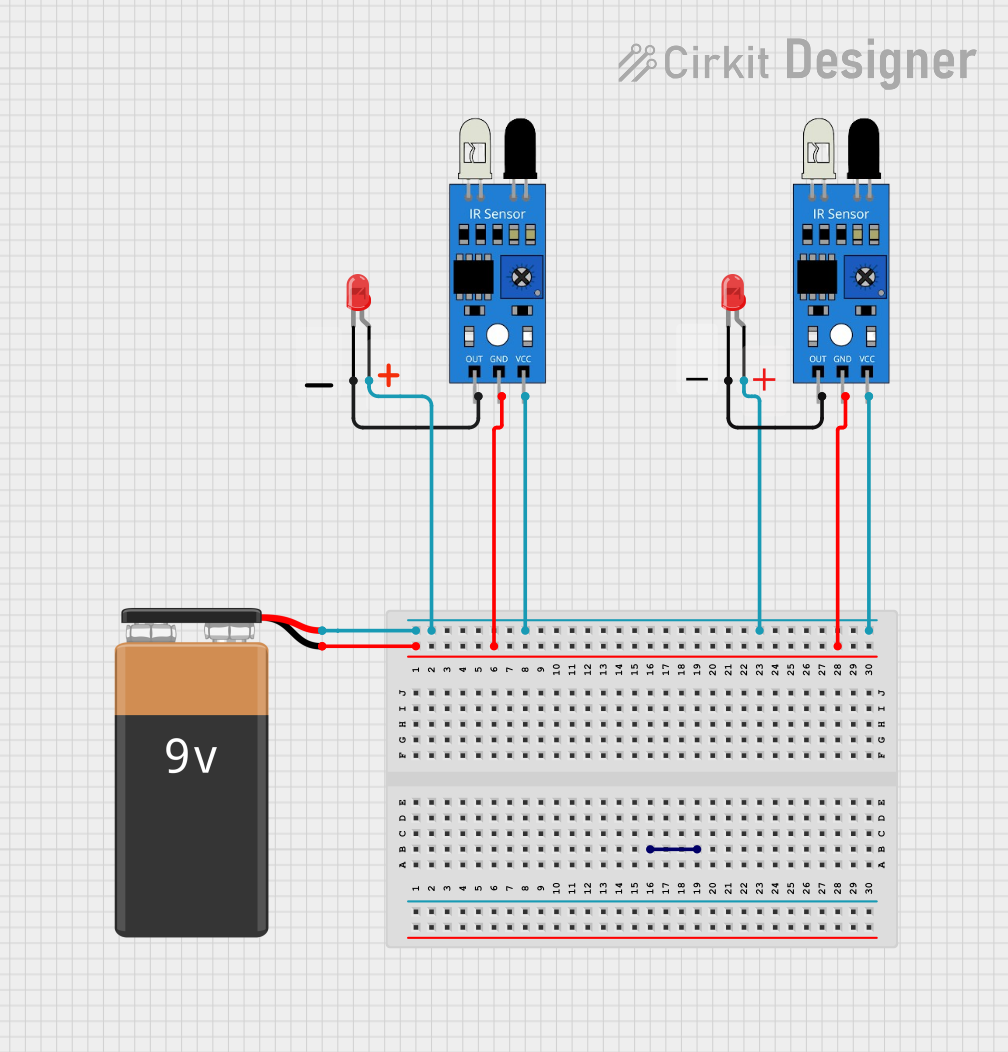
This circuit consists of two IR sensors and two red LEDs powered by a 9V battery. The IR sensors are used to detect objects, and upon detection, they trigger the LEDs to light up. The circuit is designed to demonstrate a simple object detection and indication system.
Component List
IR Sensor
- Pins:
out,gnd,vcc - Description: Infrared sensor used for object detection.
- Purpose: Detects objects and sends a signal to the LED.
- Pins:
LED: Two Pin (red)
- Pins:
cathode,anode - Description: Red light-emitting diode.
- Purpose: Lights up when the IR sensor detects an object.
- Pins:
9V Battery
- Pins:
-,+ - Description: Power source for the circuit.
- Purpose: Provides the necessary voltage to power the components.
- Pins:
Wiring Details
IR Sensor 1
- Pin
out: Connected to thecathodeof LED 1. - Pin
gnd: Connected to thegndof IR Sensor 2 and the-pin of the 9V Battery. - Pin
vcc: Connected to thevccof IR Sensor 2, theanodeof LED 1, theanodeof LED 2, and the+pin of the 9V Battery.
IR Sensor 2
- Pin
out: Connected to thecathodeof LED 2. - Pin
gnd: Connected to thegndof IR Sensor 1 and the-pin of the 9V Battery. - Pin
vcc: Connected to thevccof IR Sensor 1, theanodeof LED 1, theanodeof LED 2, and the+pin of the 9V Battery.
LED 1
- Pin
cathode: Connected to theoutpin of IR Sensor 1. - Pin
anode: Connected to thevccof IR Sensor 1, thevccof IR Sensor 2, theanodeof LED 2, and the+pin of the 9V Battery.
LED 2
- Pin
cathode: Connected to theoutpin of IR Sensor 2. - Pin
anode: Connected to thevccof IR Sensor 1, thevccof IR Sensor 2, theanodeof LED 1, and the+pin of the 9V Battery.
9V Battery
- Pin
-: Connected to thegndof IR Sensor 1 and thegndof IR Sensor 2. - Pin
+: Connected to thevccof IR Sensor 1, thevccof IR Sensor 2, theanodeof LED 1, and theanodeof LED 2.
Code
No microcontroller code is provided for this circuit.