
Arduino Uno R3 Based Ultrasonic Distance Measurement with RF Transmission
View and Edit Project In Cirkit Designer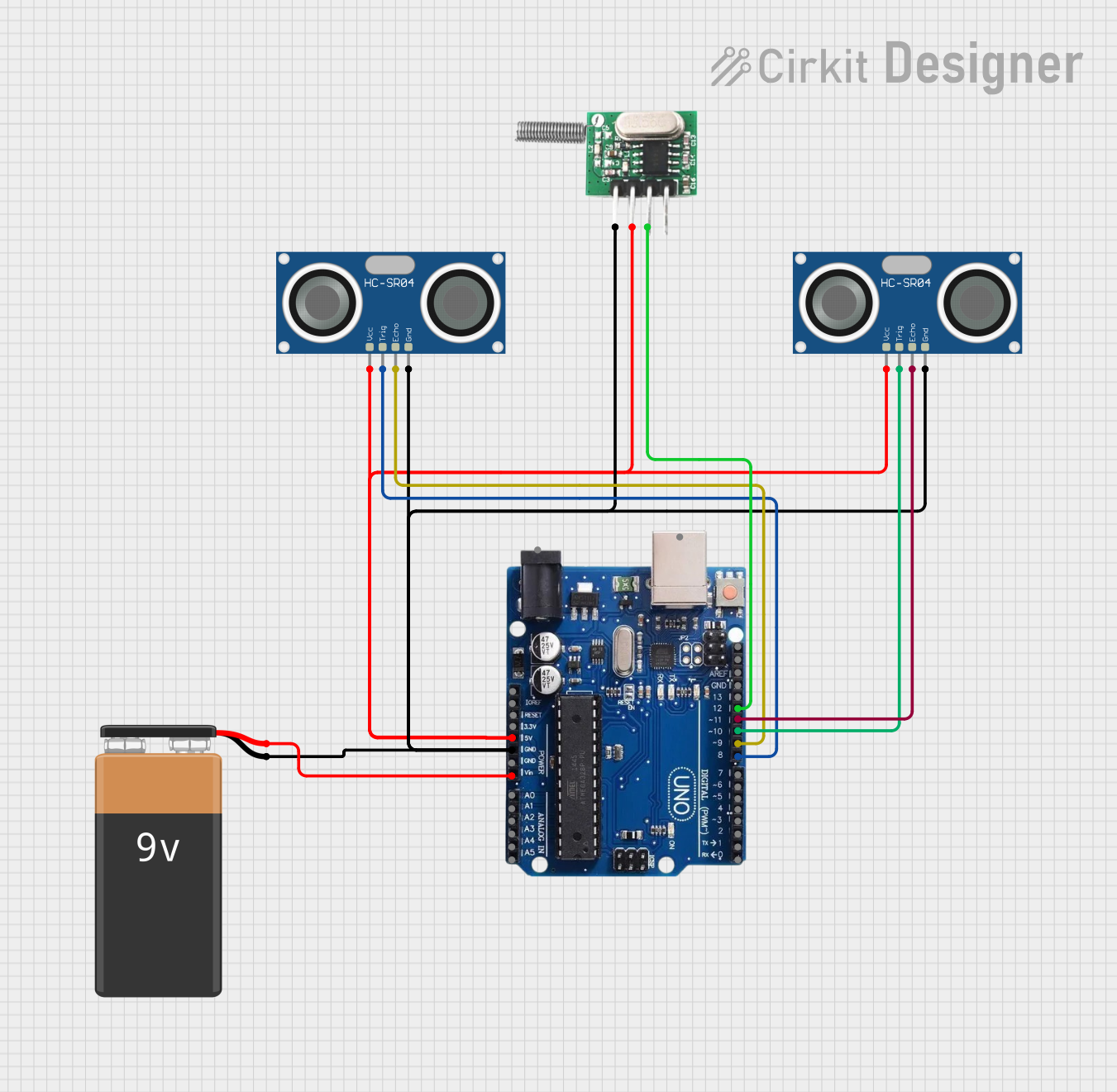
Circuit Documentation
Summary of the Circuit
This circuit is designed to interface an Arduino Uno R3 with two HC-SR04 Ultrasonic Sensors and an RF 433 MHz Transmitter. The Arduino Uno is powered by a 9V battery connected to its VIN pin, and it supplies power to the other components through its 5V and GND pins. The ultrasonic sensors are used to measure distances, and their trigger and echo pins are connected to specific digital I/O pins on the Arduino. The RF transmitter is interfaced with the Arduino to send data wirelessly, connected to one of the digital I/O pins for data transmission.
Component List
Arduino Uno R3
- Microcontroller board based on the ATmega328P
- Features digital I/O pins, analog input pins, a USB connection for programming, and power supply options
- Used as the central controller for the circuit
HC-SR04 Ultrasonic Sensor (x2)
- Ultrasonic distance measuring module
- Features VCC, TRIG, ECHO, and GND pins
- Used to measure distances by emitting ultrasonic waves and measuring the time taken for the echo to return
RF 433 MHz Transmitter
- Wireless transmitter module operating at 433 MHz
- Features -ve (GND), Data, and +ve (VCC) pins
- Used to transmit data wirelessly from the Arduino to a compatible RF receiver
9V Battery
- Standard 9V battery
- Provides power to the Arduino Uno R3
Wiring Details
Arduino Uno R3
- Power Supply:
- VIN connected to the 9V battery's positive terminal
- GND connected to the 9V battery's negative terminal, the GND pins of both HC-SR04 sensors, and the -ve pin of the RF transmitter
- 5V pin provides power to the VCC pins of both HC-SR04 sensors and the +ve pin of the RF transmitter
- I/O Connections:
- Digital pin 12 connected to the Data pin of the RF transmitter
- Digital pin 11 connected to the ECHO pin of one HC-SR04 sensor
- Digital pin 10 connected to the TRIG pin of one HC-SR04 sensor
- Digital pin 9 connected to the ECHO pin of the other HC-SR04 sensor
- Digital pin 8 connected to the TRIG pin of the other HC-SR04 sensor
HC-SR04 Ultrasonic Sensor
- VCC connected to the 5V output from the Arduino Uno R3
- GND connected to the GND on the Arduino Uno R3
- TRIG and ECHO pins connected to specified digital I/O pins on the Arduino Uno R3
RF 433 MHz Transmitter
- +ve connected to the 5V output from the Arduino Uno R3
- -ve connected to the GND on the Arduino Uno R3
- Data connected to digital pin 12 on the Arduino Uno R3
9V Battery
- Positive terminal connected to the VIN pin on the Arduino Uno R3
- Negative terminal connected to the GND pin on the Arduino Uno R3
Documented Code
No code was provided for the microcontrollers in the circuit. To fully utilize this circuit, embedded code for the Arduino Uno R3 is required to handle the initialization and operation of the HC-SR04 Ultrasonic Sensors and the RF 433 MHz Transmitter. The code would typically include setup routines, sensor reading functions, data processing, and RF data transmission routines.