
Arduino-Based Fire and Smoke Detection System with Buzzer and LED Indicators
View and Edit Project In Cirkit Designer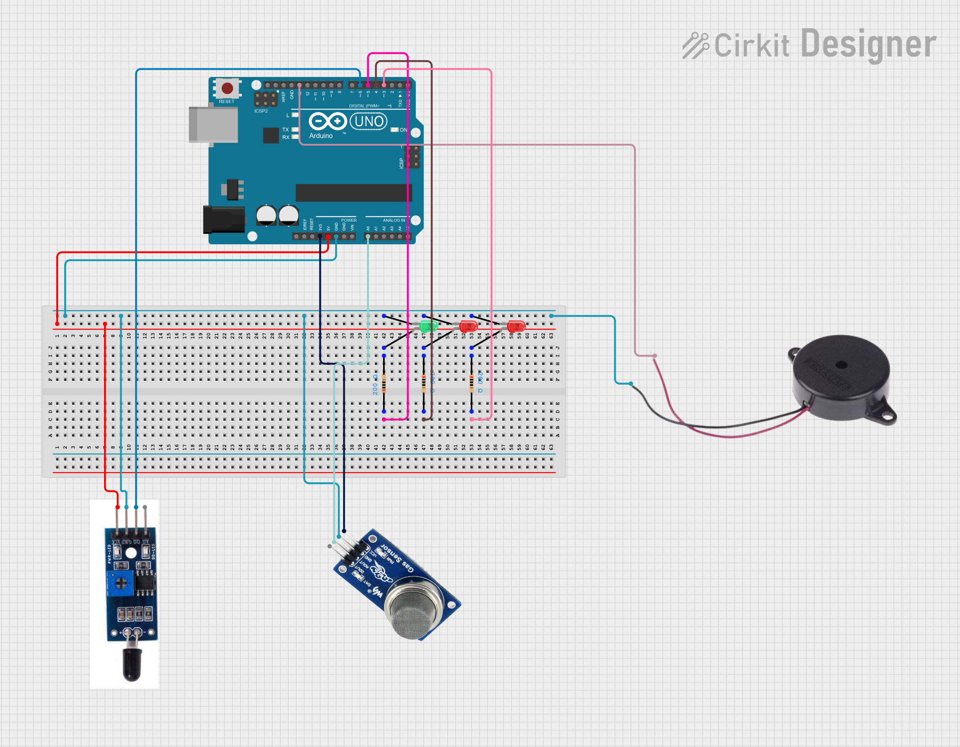
Circuit Documentation
Summary
This circuit is designed to detect fire and smoke using a heat flame sensor and an MQ2 gas sensor. It provides visual and auditory alerts through LEDs and a buzzer. The circuit is controlled by an Arduino UNO microcontroller, which processes the sensor inputs and drives the output components accordingly.
Component List
Buzzer
- Pins: POSITIVE, NEGATIVE
- Description: Emits sound when activated.
- Purpose: Provides an auditory alert when fire or smoke is detected.
Heat Flame Sensor
- Pins: AO, DO, GND, VCC
- Description: Detects the presence of flame.
- Purpose: Provides a digital output indicating the presence of flame.
MQ2 Gas Sensor
- Pins: VCC, GND, AOUT, DOUT
- Description: Detects smoke and other gases.
- Purpose: Provides an analog output indicating the level of smoke or gas.
Arduino UNO
- Pins: UNUSED, IOREF, Reset, 3.3V, 5V, GND, Vin, A0, A1, A2, A3, A4, A5, SCL, SDA, AREF, D13, D12, D11, D10, D9, D8, D7, D6, D5, D4, D3, D2, D1, D0
- Description: Microcontroller board.
- Purpose: Controls the circuit by processing sensor inputs and driving the output components.
LED: Two Pin (green)
- Pins: cathode, anode
- Description: Green LED.
- Purpose: Indicates normal operation when no fire or smoke is detected.
LED: Two Pin (red)
- Pins: cathode, anode
- Description: Red LED.
- Purpose: Indicates the presence of fire or smoke.
Resistor
- Pins: pin1, pin2
- Description: 200 Ohms resistor.
- Purpose: Limits current to the LEDs.
Wiring Details
Buzzer
- POSITIVE connected to D13 of Arduino UNO
- NEGATIVE connected to GND of Arduino UNO
Heat Flame Sensor
- VCC connected to 5V of Arduino UNO
- GND connected to GND of Arduino UNO
- DO connected to D6 of Arduino UNO
MQ2 Gas Sensor
- VCC connected to 3.3V of Arduino UNO
- GND connected to GND of Arduino UNO
- AOUT connected to A0 of Arduino UNO
Arduino UNO
- D5 connected to pin1 of Resistor (green LED)
- D4 connected to pin2 of Resistor (red LED for smoke)
- D3 connected to pin2 of Resistor (red LED for fire)
- 5V connected to VCC of Heat Flame Sensor
- GND connected to GND of Heat Flame Sensor, MQ2, Buzzer, cathode of green LED, cathode of red LED (fire), cathode of red LED (smoke)
- 3.3V connected to VCC of MQ2
- A0 connected to AOUT of MQ2
- D6 connected to DO of Heat Flame Sensor
- D13 connected to POSITIVE of Buzzer
LED: Two Pin (green)
- anode connected to pin2 of Resistor (green LED)
- cathode connected to GND of Arduino UNO
LED: Two Pin (red) (fire)
- anode connected to pin1 of Resistor (red LED for fire)
- cathode connected to GND of Arduino UNO
LED: Two Pin (red) (smoke)
- anode connected to pin1 of Resistor (red LED for smoke)
- cathode connected to GND of Arduino UNO
Resistor (green LED)
- pin1 connected to D5 of Arduino UNO
- pin2 connected to anode of green LED
Resistor (red LED for fire)
- pin1 connected to anode of red LED (fire)
- pin2 connected to D3 of Arduino UNO
Resistor (red LED for smoke)
- pin1 connected to anode of red LED (smoke)
- pin2 connected to D4 of Arduino UNO
Code Documentation
// Pin definitions
const int flameSensorPin = 6; // Digital pin connected to flame sensor DO
const int smokeSensorPin = A0; // Analog pin connected to MQ2 AOUT
const int redLEDFirePin = 3; // Digital pin connected to red LED (fire)
const int redLEDSmokePin = 4; // Digital pin connected to red LED (smoke)
const int greenLEDPin = 5; // Digital pin connected to green LED
const int buzzerPin = 13; // Digital pin connected to buzzer

void setup() {
  // Initialize serial communication
  Serial.begin(9600);
  // Initialize pins
  pinMode(flameSensorPin, INPUT);
  pinMode(smokeSensorPin, INPUT);
  pinMode(redLEDFirePin, OUTPUT);
  pinMode(redLEDSmokePin, OUTPUT);
  pinMode(greenLEDPin, OUTPUT);
  pinMode(buzzerPin, OUTPUT);
  // Turn on green LED initially
  digitalWrite(greenLEDPin, HIGH);
}

void loop() {
  // Read sensor values
  int flameState = digitalRead(flameSensorPin);
  int smokeLevel = analogRead(smokeSensorPin);

  // Print sensor values for debugging
  Serial.print("Flame State: ");
  Serial.println(flameState);
  Serial.print("Smoke Level: ");
  Serial.println(smokeLevel);

  // Check for fire or smoke
  if (flameState == HIGH || smokeLevel > 300) { // Adjust threshold as needed
    // Fire or smoke detected
    digitalWrite(greenLEDPin, LOW); // Turn off green LED

    if (flameState == HIGH && smokeLevel > 300) {
      // Both fire and smoke detected
      digitalWrite(redLEDFirePin, HIGH); // Turn on red LED (fire)
      digitalWrite(redLEDSmokePin, HIGH); // Turn on red LED (smoke)
      tone(buzzerPin, 1000); // Set buzzer to high tone
    } else if (flameState == HIGH) {
      // Only fire detected
      digitalWrite(redLEDFirePin, HIGH); // Turn on red LED (fire)
      digitalWrite(redLEDSmokePin, LOW); // Turn off red LED (smoke)
      tone(buzzerPin, 500); // Set buzzer to medium tone
    } else if (smokeLevel > 300) {
      // Only smoke detected
      digitalWrite(redLEDFirePin, LOW); // Turn off red LED (fire)
      digitalWrite(redLEDSmokePin, HIGH); // Turn on red LED (smoke)
      tone(buzzerPin, 250); // Set buzzer to low tone
    }
  } else {
    // No fire or smoke detected
    digitalWrite(greenLEDPin, HIGH); // Turn on green LED
    digitalWrite(redLEDFirePin, LOW); // Turn off red LED (fire)
    digitalWrite(redLEDSmokePin, LOW); // Turn off red LED (smoke)
    noTone(buzzerPin); // Turn off buzzer
  }

  // Small delay for stability
  delay(100);
}
This code initializes the pins connected to the sensors, LEDs, and buzzer. It continuously reads the sensor values and updates the LEDs and buzzer based on the presence of fire or smoke. The green LED indicates normal operation, while the red LEDs and buzzer provide alerts for fire and smoke.