
Arduino Nano Controlled Ultrasonic Parking Assistant with LED Indicators and LCD Display
View and Edit Project In Cirkit Designer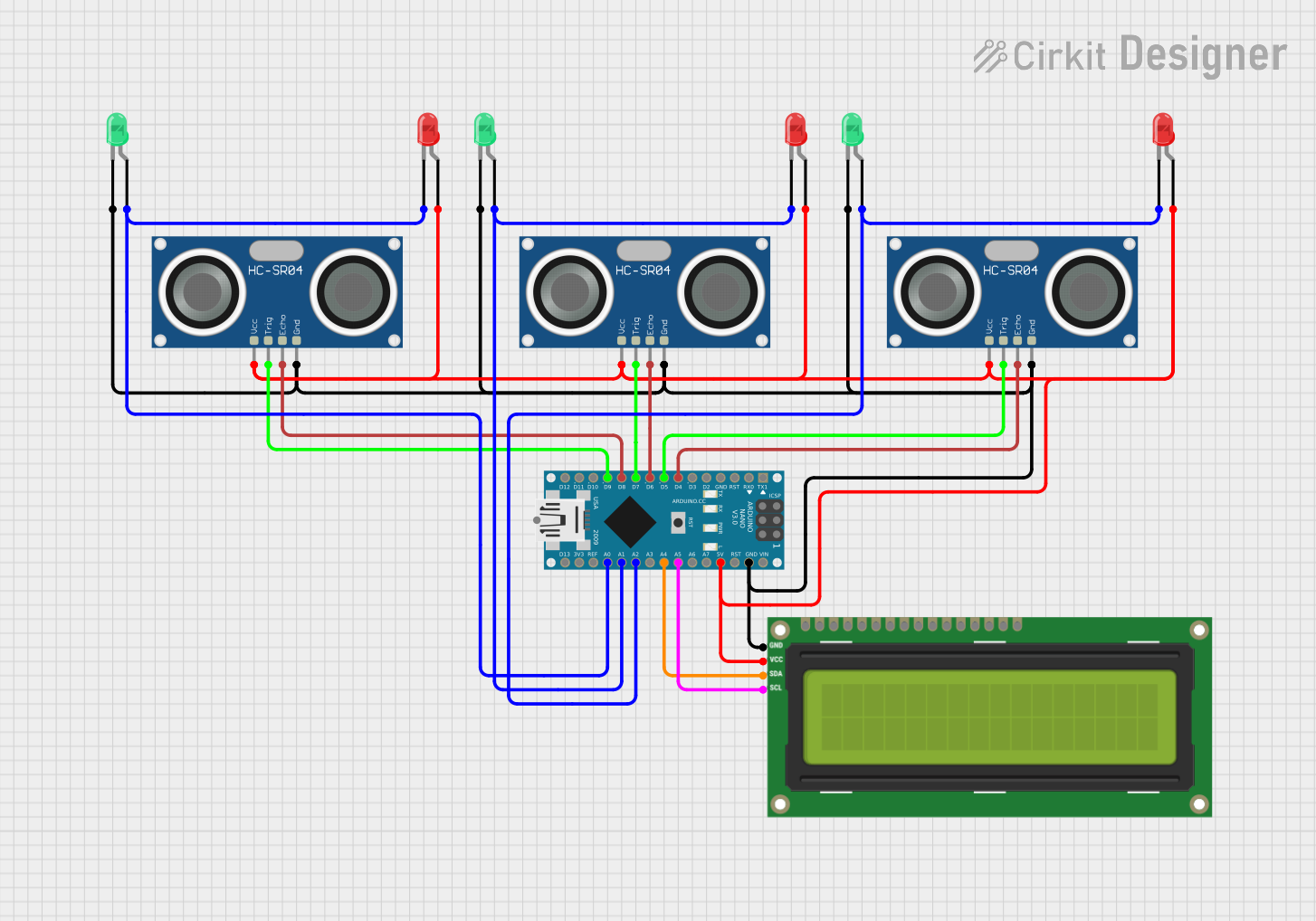
Circuit Documentation
Summary
This circuit is designed to monitor parking slots using HC-SR04 Ultrasonic Sensors and indicate their status using LEDs. The circuit includes an Arduino Nano microcontroller, which controls the sensors and LEDs, and displays the status of each parking slot on two I2C LCD screens. The ultrasonic sensors detect the presence of a vehicle in a parking slot, and the corresponding LED (red for occupied, green for empty) indicates the slot's status. The LCD screens provide a textual display of each slot's occupancy.
Component List
HC-SR04 Ultrasonic Sensor
- Description: Ultrasonic distance sensor.
- Pins: VCC, TRIG, ECHO, GND.
LED: Two Pin (red)
- Description: Red indicator LED.
- Pins: cathode, anode.
LED: Two Pin (green)
- Description: Green indicator LED.
- Pins: cathode, anode.
I2C LCD 16x2 Screen
- Description: 16x2 character LCD screen with I2C communication.
- Pins: SCL, SDA, VCC (5V), GND, VDD, VO, RS, RW, E, D0, D1, D2, D3, D4, D5, D6, D7, BLA, BLK.
Arduino Nano
- Description: Compact microcontroller board based on the ATmega328P.
- Pins: D1/TX, D0/RX, RESET, GND, D2, D3, D4, D5, D6, D7, D8, D9, D10, D11/MOSI, D12/MISO, VIN, 5V, A7, A6, A5, A4, A3, A2, A1, A0, AREF, 3V3, D13/SCK.
Wiring Details
HC-SR04 Ultrasonic Sensor
- VCC: Connected to 5V power supply.
- TRIG: Connected to a digital pin on the Arduino Nano for triggering the distance measurement.
- ECHO: Connected to a digital pin on the Arduino Nano to receive the distance measurement signal.
- GND: Connected to the ground.
LED: Two Pin (red/green)
- cathode: Connected to the ground or a digital pin on the Arduino Nano for controlling the LED state.
- anode: Connected to the 5V power supply or a digital pin on the Arduino Nano through a current-limiting resistor.
I2C LCD 16x2 Screen
- SCL: Connected to the A5 pin on the Arduino Nano for I2C clock.
- SDA: Connected to the A4 pin on the Arduino Nano for I2C data.
- VCC (5V): Connected to the 5V power supply.
- GND: Connected to the ground.
Arduino Nano
- Digital Pins (D2-D9): Connected to the TRIG and ECHO pins of the HC-SR04 Ultrasonic Sensors.
- Digital Pins (D10-D13, A0-A3): Connected to the anodes of the LEDs through current-limiting resistors.
- Analog Pins (A4, A5): Used for I2C communication with the LCD screen.
- 5V and GND: Provide power to the sensors, LEDs, and LCD screen.
Documented Code
#include <Wire.h>
#include <LiquidCrystal_I2C.h>

// Initialize the LCD objects for two LCDs with their I2C addresses
LiquidCrystal_I2C lcd1(0x27, 16, 2);
LiquidCrystal_I2C lcd2(0x26, 16, 2);

// Define pins for ultrasonic sensors
const int trigPin1 = 2;
const int echoPin1 = 3;
const int trigPin2 = 4;
const int echoPin2 = 5;
const int trigPin3 = 6;
const int echoPin3 = 7;
const int trigPin4 = 8;
const int echoPin4 = 9;

// Define pins for LEDs
const int redLED1 = 10;
const int redLED2 = 11;
const int redLED3 = 12;
const int redLED4 = 13;
const int greenLED1 = A0;
const int greenLED2 = A1;
const int greenLED3 = A2;
const int greenLED4 = A3;

long duration;
int distance;

void setup() {
  // Initialize the LCDs
  lcd1.init();
  lcd2.init();

  lcd1.backlight();
  lcd2.backlight();

  lcd1.setCursor(0, 0);
  lcd1.print("Slot 1:");

  lcd1.setCursor(0, 1);
  lcd1.print("Slot 2:");

  lcd2.setCursor(0, 0);
  lcd2.print("Slot 3:");

  lcd2.setCursor(0, 1);
  lcd2.print("Slot 4:");

  // Initialize pins for ultrasonic sensors
  pinMode(trigPin1, OUTPUT);
  pinMode(echoPin1, INPUT);
  pinMode(trigPin2, OUTPUT);
  pinMode(echoPin2, INPUT);
  pinMode(trigPin3, OUTPUT);
  pinMode(echoPin3, INPUT);
  pinMode(trigPin4, OUTPUT);
  pinMode(echoPin4, INPUT);

  // Initialize pins for LEDs
  pinMode(redLED1, OUTPUT);
  pinMode(redLED2, OUTPUT);
  pinMode(redLED3, OUTPUT);
  pinMode(redLED4, OUTPUT);
  pinMode(greenLED1, OUTPUT);
  pinMode(greenLED2, OUTPUT);
  pinMode(greenLED3, OUTPUT);
  pinMode(greenLED4, OUTPUT);
}

void loop() {
  // Check parking slot 1
  int distance1 = getDistance(trigPin1, echoPin1);
  lcd1.setCursor(8, 0);
  if (distance1 < 10) {
    lcd1.print("Occupied");
    digitalWrite(redLED1, HIGH);
    digitalWrite(greenLED1, LOW);
  } else {
    lcd1.print("Empty   ");
    digitalWrite(redLED1, LOW);
    digitalWrite(greenLED1, HIGH);
  }

  // Check parking slot 2
  int distance2 = getDistance(trigPin2, echoPin2);
  lcd1.setCursor(8, 1);
  if (distance2 < 10) {
    lcd1.print("Occupied");
    digitalWrite(redLED2, HIGH);
    digitalWrite(greenLED2, LOW);
  } else {
    lcd1.print("Empty   ");
    digitalWrite(redLED2, LOW);
    digitalWrite(greenLED2, HIGH);
  }

  // Check parking slot 3
  int distance3 = getDistance(trigPin3, echoPin3);
  lcd2.setCursor(8, 0);
  if (distance3 < 10) {
    lcd2.print("Occupied");
    digitalWrite(redLED3, HIGH);
    digitalWrite(greenLED3, LOW);
  } else {
    lcd2.print("Empty   ");
    digitalWrite(redLED3, LOW);
    digitalWrite(greenLED3, HIGH);
  }

  // Check parking slot 4
  int distance4 = getDistance(trigPin4, echoPin4);
  lcd2.setCursor(8, 1);
  if (distance4 < 10) {
    lcd2.print("Occupied");
    digitalWrite(redLED4, HIGH);
    digitalWrite(greenLED4, LOW);
  } else {
    lcd2.print("Empty   ");
    digitalWrite(redLED4, LOW);
    digitalWrite(greenLED4, HIGH);
  }

  delay(1000);  // Update every second
}

// Function to get the distance measured by the ultrasonic sensor
int getDistance(int trigPin, int echoPin) {
  digitalWrite(trigPin, LOW);
  delayMicroseconds(2);
  digitalWrite(trigPin, HIGH);
  delayMicroseconds(10);
  digitalWrite(trigPin, LOW);

  duration = pulseIn(echoPin, HIGH);
  distance = duration * 0.034 / 2;

  return distance;
}
This code is responsible for controlling the ultrasonic sensors and LEDs, as well as updating the LCD screens with the status of each parking slot. The getDistance function calculates the distance to an object using the ultrasonic sensor by sending a pulse and measuring the time it takes for the echo to return. The main loop checks each parking slot and updates the LCD and LED status accordingly.