Cirkit Designer
Your all-in-one circuit design IDE
Home /
Project Documentation
Arduino UNO LED Blinker with Battery Power
Circuit Documentation
Summary
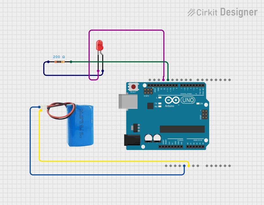
This circuit consists of an Arduino UNO microcontroller, a red LED, a 5V battery, and a 200 Ohm resistor. The Arduino UNO is powered by the 5V battery and controls the LED, which is connected through the resistor to limit the current.
Component List
Arduino UNO
- Description: A microcontroller board based on the ATmega328P.
- Pins: UNUSED, IOREF, Reset, 3.3V, 5V, GND, Vin, A0, A1, A2, A3, A4, A5, SCL, SDA, AREF, D13, D12, D11, D10, D9, D8, D7, D6, D5, D4, D3, D2, D1, D0
LED: Two Pin (red)
- Description: A red light-emitting diode.
- Pins: cathode, anode
5V Battery
- Description: A power source providing 5 volts.
- Pins: positive, negative
Resistor
- Description: A 200 Ohm resistor used to limit current.
- Pins: pin1, pin2
- Properties:
- Resistance: 200 Ohms
Wiring Details
Arduino UNO
- 5V connected to positive of the 5V Battery
- GND connected to negative of the 5V Battery
- GND connected to cathode of the LED
- D13 connected to pin2 of the Resistor
LED: Two Pin (red)
- cathode connected to GND of the Arduino UNO
- anode connected to pin1 of the Resistor
5V Battery
- positive connected to 5V of the Arduino UNO
- negative connected to GND of the Arduino UNO
Resistor
- pin1 connected to anode of the LED
- pin2 connected to D13 of the Arduino UNO
Code
Arduino UNO Code (sketch.ino)
void setup() {
  // put your setup code here, to run once:
  pinMode(13, OUTPUT);
}

void loop() {
  // put your main code here, to run repeatedly:
  digitalWrite(13, HIGH);
  delay(1000);
  digitalWrite(13, LOW);
  delay(1000);
}
This code sets up pin 13 as an output and toggles it high and low every second, causing the LED to blink.