
Arduino UNO Vape Detection System with LCD Display and Fan Control
View and Edit Project In Cirkit Designer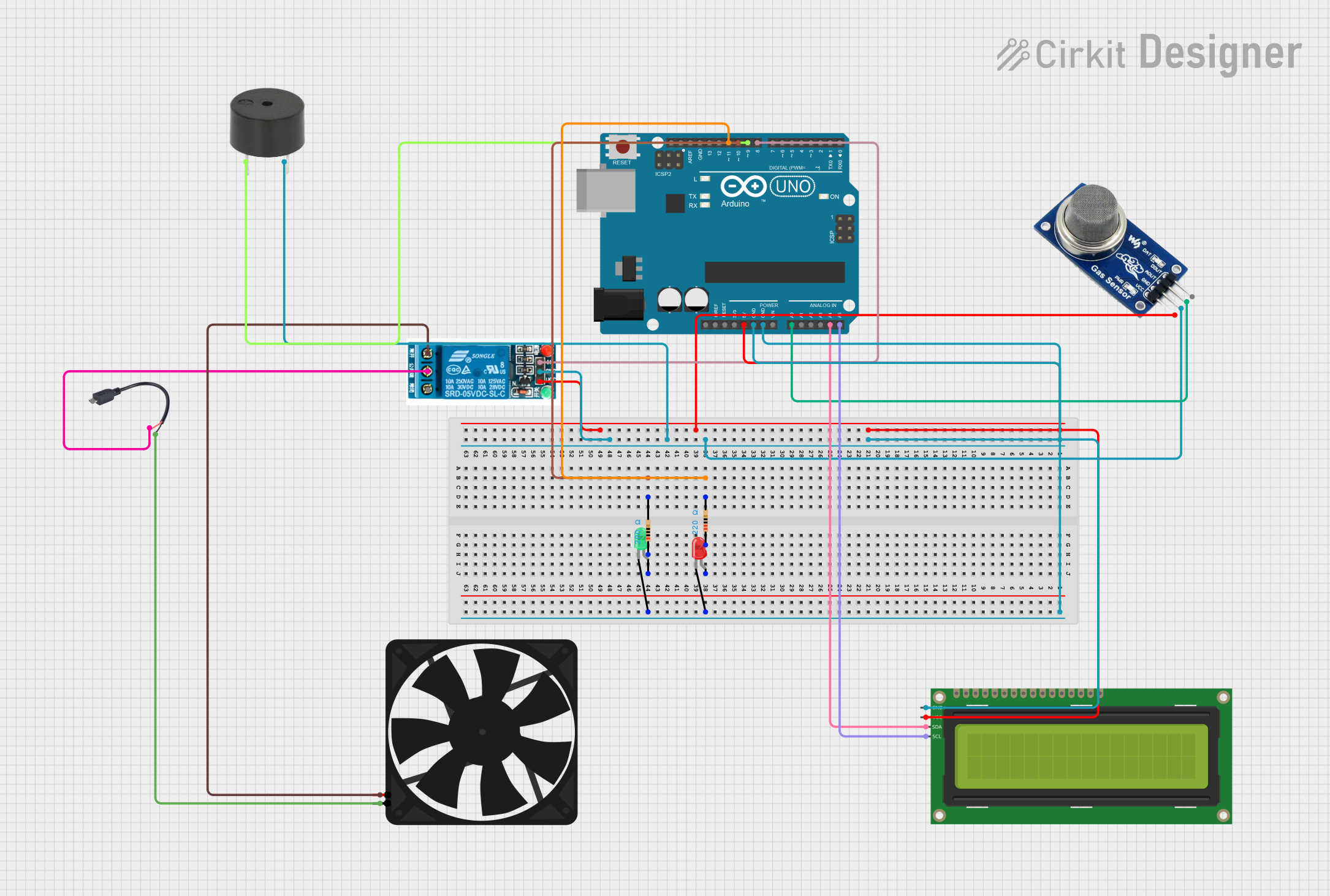
Circuit Documentation
Summary
This circuit is designed to detect smoke using an MQ2 sensor and respond by activating a fan and a buzzer. The system also includes an LCD display to show the smoke level and status. The Arduino UNO microcontroller is used to control the components and process the sensor data.
Component List
Arduino UNO
- Description: Microcontroller board based on the ATmega328P.
- Pins: UNUSED, IOREF, Reset, 3.3V, 5V, GND, Vin, A0, A1, A2, A3, A4, A5, SCL, SDA, AREF, D13, D12, D11, D10, D9, D8, D7, D6, D5, D4, D3, D2, D1, D0
5V Relay
- Description: Relay module to control high voltage devices.
- Pins: Normally Open, Common terminal, Normally Closed, In, GND, VCC
Micro USB to Cable (2 Pin)
- Description: Provides power to the circuit.
- Pins: Micro USB, +, -
16x2 I2C LCD
- Description: LCD display with I2C interface.
- Pins: GND, VCC, SDA, SCL
LED: Two Pin (red)
- Description: Red LED.
- Pins: cathode, anode
LED: Two Pin (green)
- Description: Green LED.
- Pins: cathode, anode
MQ2
- Description: Gas sensor to detect smoke.
- Pins: VCC, GND, AOUT, DOUT
Fan
- Description: Cooling fan.
- Pins: GND, 5V
Buzzer
- Description: Buzzer for audio alert.
- Pins: PIN, GND
Resistor (200 Ohms)
- Description: Resistor with 200 Ohms resistance.
- Pins: pin1, pin2
Resistor (220 Ohms)
- Description: Resistor with 220 Ohms resistance.
- Pins: pin1, pin2
Wiring Details
Arduino UNO
- 5V: Connected to VCC of 16x2 I2C LCD, VCC of MQ2, VCC of 5V Relay
- GND: Connected to GND of 16x2 I2C LCD, GND of MQ2, GND of Buzzer, GND of 5V Relay, cathode of Red LED, cathode of Green LED
- A0: Connected to AOUT of MQ2
- A4: Connected to SDA of 16x2 I2C LCD
- A5: Connected to SCL of 16x2 I2C LCD
- D8: Connected to In of 5V Relay
- D9: Connected to PIN of Buzzer
- D10: Connected to pin2 of 200 Ohms Resistor
- D11: Connected to pin2 of 220 Ohms Resistor
5V Relay
- VCC: Connected to 5V of Arduino UNO
- GND: Connected to GND of Arduino UNO
- In: Connected to D8 of Arduino UNO
- Normally Open: Connected to 5V of Fan
- Common terminal: Connected to + of Micro USB to Cable (2 Pin)
Micro USB to Cable (2 Pin)
- +: Connected to Common terminal of 5V Relay
- -: Connected to GND of Fan
16x2 I2C LCD
- VCC: Connected to 5V of Arduino UNO
- GND: Connected to GND of Arduino UNO
- SDA: Connected to A4 of Arduino UNO
- SCL: Connected to A5 of Arduino UNO
MQ2
- VCC: Connected to 5V of Arduino UNO
- GND: Connected to GND of Arduino UNO
- AOUT: Connected to A0 of Arduino UNO
Fan
- 5V: Connected to Normally Open of 5V Relay
- GND: Connected to - of Micro USB to Cable (2 Pin)
Buzzer
- PIN: Connected to D9 of Arduino UNO
- GND: Connected to GND of Arduino UNO
LED: Two Pin (red)
- cathode: Connected to GND of Arduino UNO
- anode: Connected to pin1 of 220 Ohms Resistor
LED: Two Pin (green)
- cathode: Connected to GND of Arduino UNO
- anode: Connected to pin1 of 200 Ohms Resistor
Resistor (200 Ohms)
- pin1: Connected to anode of Green LED
- pin2: Connected to D10 of Arduino UNO
Resistor (220 Ohms)
- pin1: Connected to anode of Red LED
- pin2: Connected to D11 of Arduino UNO
Code Documentation
#include <Wire.h>
#include <LiquidCrystal_I2C.h>

// Initialize the LCD (address 0x27, 16 columns, 2 rows)
LiquidCrystal_I2C lcd(0x27, 16, 2);

// Pin Definitions
const int mq2AoutPin = A0;    // MQ2 analog output pin
const int relayPin = 8;       // Relay module control pin
const int buzzerPin = 9;      // Buzzer pin
const int smokeThreshold = 300; // Smoke threshold (adjust based on testing)

void setup() {
  // Initialize LCD
  lcd.init();
  lcd.backlight();

  // Pin Modes
  pinMode(mq2AoutPin, INPUT);
  pinMode(relayPin, OUTPUT);
  pinMode(buzzerPin, OUTPUT);

  // Initial States
  digitalWrite(relayPin, LOW); // Fan off
  digitalWrite(buzzerPin, LOW); // Buzzer off

  // Display Initial Message
  lcd.setCursor(0, 0);
  lcd.print("Vape Detection");
  lcd.setCursor(0, 1);
  lcd.print("Initializing...");
  delay(2000);
  lcd.clear();
}

void loop() {
  // Read the analog value from MQ2
  int smokeValue = analogRead(mq2AoutPin);

  // Display smoke level on LCD
  lcd.setCursor(0, 0);
  lcd.print("Smoke Level: ");
  lcd.print(smokeValue);

  // Check smoke threshold
  if (smokeValue > smokeThreshold) {
    // Smoke detected
    lcd.setCursor(0, 1);
    lcd.print("Status: ALERT!");
    digitalWrite(relayPin, HIGH); // Turn on fan
    digitalWrite(buzzerPin, HIGH); // Activate buzzer
  } else {
    // No smoke detected
    lcd.setCursor(0, 1);
    lcd.print("Status: Safe  ");
    digitalWrite(relayPin, LOW); // Turn off fan
    digitalWrite(buzzerPin, LOW); // Deactivate buzzer
  }

  // Add a short delay to avoid rapid fluctuations
  delay(500);
}
This code initializes the LCD, sets up the pin modes, and continuously reads the smoke level from the MQ2 sensor. If the smoke level exceeds the threshold, it activates the fan and buzzer and displays an alert message on the LCD. If the smoke level is below the threshold, it deactivates the fan and buzzer and displays a safe status on the LCD.