
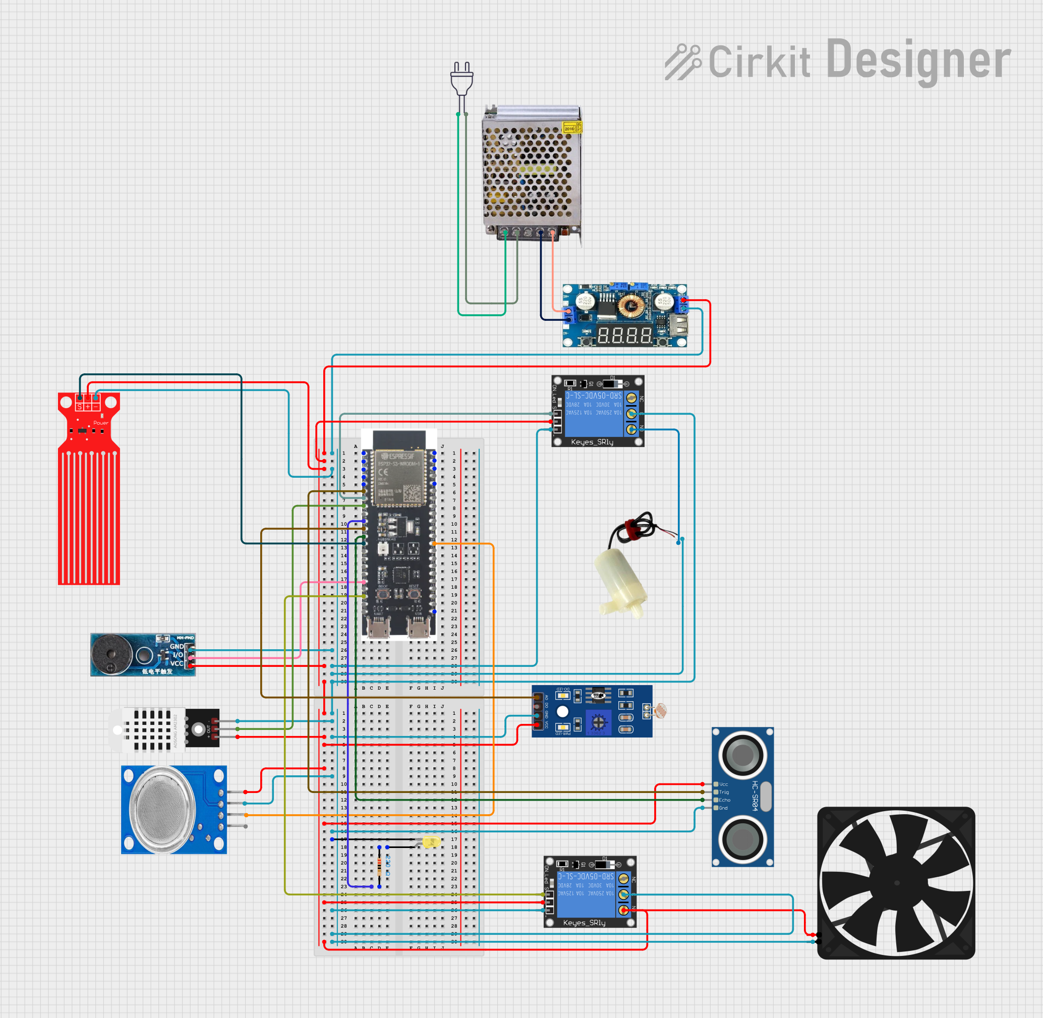
Circuit Documentation
Summary
This document provides a detailed overview of a circuit that integrates various sensors, actuators, and a microcontroller (ESP32-S3) to monitor environmental conditions and control devices such as a water pump, fan, and buzzer. The circuit includes components like a power supply, step-down regulator, relays, sensors (DHT22, MQ135, LDR, HC-SR04), and actuators (water pump, fan, buzzer, LED). The ESP32-S3 microcontroller is programmed to read sensor data and control the actuators based on predefined conditions.
Component List
ESP32-S3
- Description: A powerful microcontroller with Wi-Fi and Bluetooth capabilities.
- Pins: 3v3, EN, GPIO4, GPIO5, GPIO6, GPIO7, GPIO15, GPIO16, GPIO17, GPIO18, GPIO8, GPIO46, GPIO9, GPIO10, GPIO11, GPIO12, GPIO13, GPIO14, 5V, GND, GPIO43, GPIO44, GPIO1, GPIO2, GPIO42, GPIO41, GPIO40, GPIO39, GPIO38, GPIO37, GPIO36, GPIO35, GPIO0, GPIO45, GPIO48, GPIO47, GPIO21, GPIO20, GPIO19
POWER SUPPLY 12V 5AMP
- Description: Provides 12V DC power from a 220V AC source.
- Pins: 220V Positive Pole (AC), 220V Negative Pole (AC), GND, GND (DC), 12V-24V Output (DC)
Regulator Stepdown DC with LCD Display
- Description: Steps down the voltage from 12V to 5V.
- Pins: IN +, IN -, OUT +, OUT -
1-Channel Relay (5V 10A)
- Description: Controls high-power devices using a low-power signal.
- Pins: NC, signal, C, power, NO, ground
5v mini water pump
- Description: A small water pump operating at 5V.
- Pins: positive pin, negative pin
power 220v
- Description: Provides 220V AC power.
- Pins: hot wire, neutral wire
Buzzer Module
- Description: Emits sound when activated.
- Pins: GND, Vcc, I/O
DHT22
- Description: Temperature and humidity sensor.
- Pins: +, Out, -
MQ135
- Description: Air quality sensor.
- Pins: VCC, GND, A0, D0
LDR
- Description: Light-dependent resistor for measuring light intensity.
- Pins: A0, D0, GND, VCC
HC-SR04 Ultrasonic Sensor
- Description: Measures distance using ultrasonic waves.
- Pins: VCC, TRIG, ECHO, GND
Fan
- Description: A small fan operating at 5V.
- Pins: GND, 5V
Resistor
- Description: 220 Ohms resistor.
- Pins: pin1, pin2
LED: Two Pin (yellow)
- Description: A yellow LED.
- Pins: cathode, anode
Water Level Sensor
- Description: Measures water level.
- Pins: SIG, VCC, GND
Wiring Details
ESP32-S3
- GPIO6 connected to HC-SR04 Ultrasonic Sensor TRIG
- GPIO7 connected to 1-Channel Relay (5V 10A) signal
- GPIO15 connected to DHT22 Out
- GPIO16 connected to Resistor pin2
- GPIO17 connected to LDR A0
- GPIO18 connected to HC-SR04 Ultrasonic Sensor ECHO
- GPIO8 connected to Water Level Sensor SIG
- GPIO12 connected to Buzzer Module I/O
- GPIO14 connected to 1-Channel Relay (5V 10A) signal
- GPIO35 connected to MQ135 A0
POWER SUPPLY 12V 5AMP
- 220V Positive Pole (AC) connected to power 220v hot wire
- 220V Negative Pole (AC) connected to power 220v neutral wire
- GND (DC) connected to Regulator Stepdown DC with LCD Display IN -
- 12V-24V Output (DC) connected to Regulator Stepdown DC with LCD Display IN +
Regulator Stepdown DC with LCD Display
- OUT + connected to:
- 1-Channel Relay (5V 10A) power
- Water Level Sensor VCC
- Buzzer Module Vcc
- DHT22 +
- LDR VCC
- MQ135 VCC
- HC-SR04 Ultrasonic Sensor VCC
- 1-Channel Relay (5V 10A) power
- Fan 5V
- 1-Channel Relay (5V 10A) NO
- OUT - connected to:
- Water Level Sensor GND
- Buzzer Module GND
- 1-Channel Relay (5V 10A) ground
- 5v mini water pump negative pin
- 1-Channel Relay (5V 10A) C
- LED: Two Pin (yellow) cathode
- DHT22 -
- LDR GND
- MQ135 GND
- HC-SR04 Ultrasonic Sensor GND
- 1-Channel Relay (5V 10A) ground
- 1-Channel Relay (5V 10A) C
- Fan GND
1-Channel Relay (5V 10A)
- NO connected to 5v mini water pump positive pin
Resistor
- pin1 connected to LED: Two Pin (yellow) anode
Documented Code
ESP32-S3 Code
#include <DHT.h>

#define DHTPIN 15 // GPIO15 for DHT22
#define DHTTYPE DHT22

const int ldrPin = 36; // GPIO36 for LDR sensor
const int soilMoisturePin = 39; // GPIO39 for Soil Moisture sensor
const int mq135Pin = 35; // GPIO35 for MQ135 sensor
const int trigPin = 6; // GPIO6 for HC-SR04 TRIG
const int echoPin = 18; // GPIO18 for HC-SR04 ECHO
const int buzzerPin = 12; // GPIO12 for Buzzer
const int ledPin = 16; // GPIO16 for LED
const int relayWaterPumpPin = 7; // GPIO7 for Relay controlling water pump
const int relayFanPin = 14; // GPIO14 for Relay controlling fan

DHT dht(DHTPIN, DHTTYPE);

void setup() {
  Serial.begin(115200);
  pinMode(ldrPin, INPUT);
  pinMode(soilMoisturePin, INPUT);
  pinMode(mq135Pin, INPUT);
  pinMode(trigPin, OUTPUT);
  pinMode(echoPin, INPUT);
  pinMode(buzzerPin, OUTPUT);
  pinMode(ledPin, OUTPUT);
  pinMode(relayWaterPumpPin, OUTPUT);
  pinMode(relayFanPin, OUTPUT);

  dht.begin();
}

void loop() {
  // Read LDR value
  int ldrValue = analogRead(ldrPin);
  Serial.print("LDR Value: ");
  Serial.println(ldrValue);

  // Read Soil Moisture value
  int soilMoistureValue = analogRead(soilMoisturePin);
  Serial.print("Soil Moisture Value: ");
  Serial.println(soilMoistureValue);

  // Read DHT22 values
  float humidity = dht.readHumidity();
  float temperature = dht.readTemperature();
  Serial.print("Humidity: ");
  Serial.print(humidity);
  Serial.print("%  Temperature: ");
  Serial.print(temperature);
  Serial.println("°C");

  // Read MQ135 value
  int mq135Value = analogRead(mq135Pin);
  Serial.print("MQ135 Value: ");
  Serial.println(mq135Value);

  // Read HC-SR04 value
  long duration, distance;
  digitalWrite(trigPin, LOW);
  delayMicroseconds(2);
  digitalWrite(trigPin, HIGH);
  delayMicroseconds(10);
  digitalWrite(trigPin, LOW);
  duration = pulseIn(echoPin, HIGH);
  distance = (duration / 2) / 29.1;
  Serial.print("Distance: ");
  Serial.print(distance);
  Serial.println(" cm");

  // Control LED based on LDR value
  if (