
Arduino UNO Controlled Obstacle Avoiding Robot with L293D Motor Driver and Ultrasonic Sensor
View and Edit Project In Cirkit Designer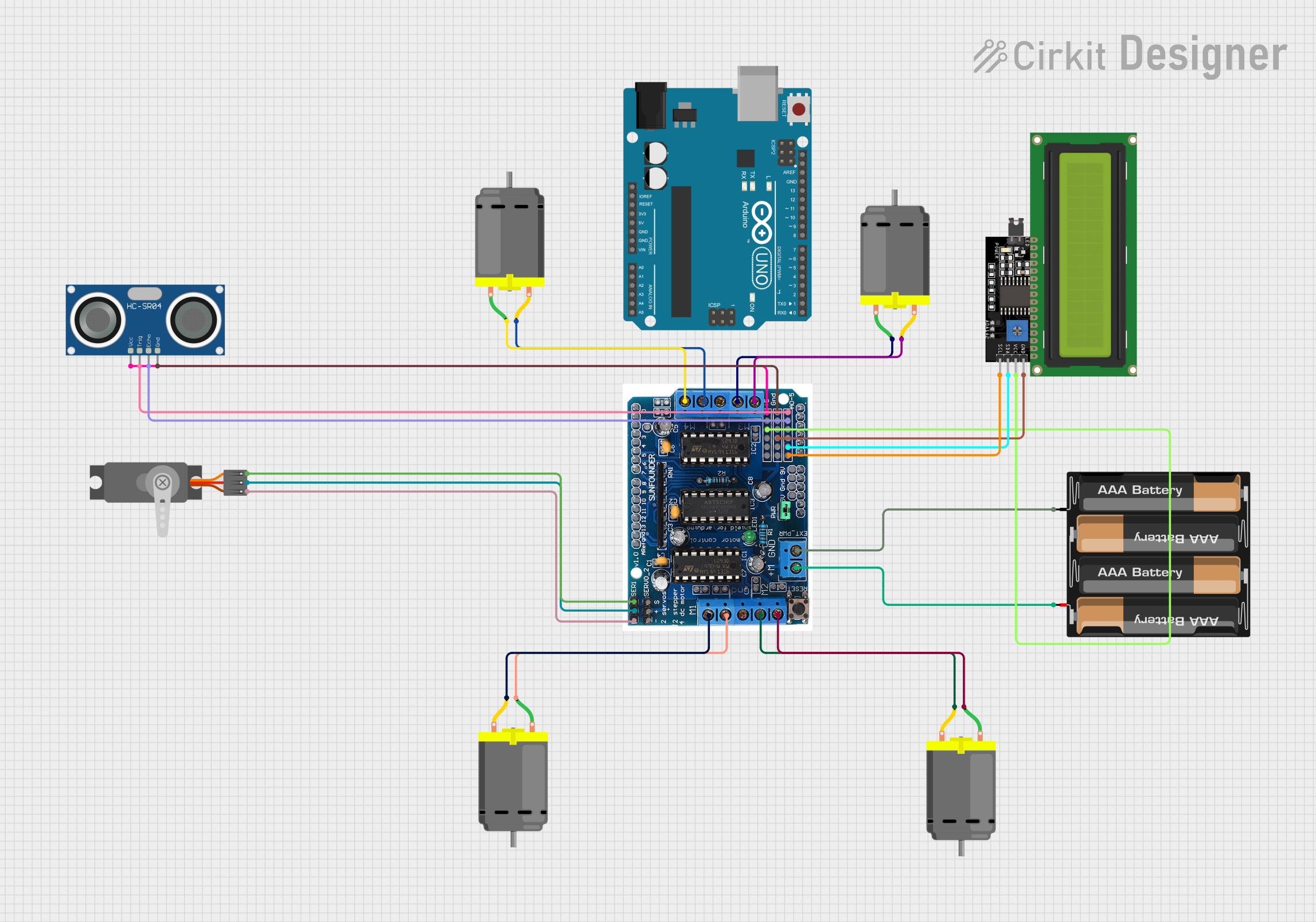
Circuit Documentation
Summary
This circuit is designed to control a robotic platform equipped with DC motors for movement, an ultrasonic sensor for distance measurement, and a servo motor for directional control of the sensor. The brain of the circuit is an Arduino UNO microcontroller, which interfaces with an L293D motor driver shield to control the motors. The circuit also includes a 4 x AAA battery mount for power and an LCD display for user interface and feedback.
Component List
L293D Motor Driver Shield
- Description: A motor driver shield that can drive up to 4 DC motors or 2 stepper motors, 2 servos, and has 6 general-purpose I/O pins.
- Purpose: To control the speed and direction of the DC motors and to provide a connection interface for the servo motor and the ultrasonic sensor.
DC Motor (x4)
- Description: A standard DC motor that converts electrical energy into mechanical energy.
- Purpose: To provide motion to the robotic platform.
4 x AAA Battery Mount
- Description: A battery holder for four AAA batteries.
- Purpose: To supply power to the motor driver shield and the motors.
Servo (Wokwi Compatible)
- Description: A servo motor capable of precise angular positioning.
- Purpose: To control the direction of the ultrasonic sensor for scanning the environment.
HC-SR04 Ultrasonic Sensor
- Description: An ultrasonic distance sensor that can measure distances by emitting ultrasonic waves and measuring the time taken for the echo to return.
- Purpose: To detect obstacles and measure the distance to them.
Arduino UNO
- Description: A microcontroller board based on the ATmega328P.
- Purpose: To serve as the central processing unit of the circuit, running the embedded code to control the motors, read sensor data, and manage the user interface.
LCD Display 16x4 I2C
- Description: A 16x4 character LCD display with an I2C interface.
- Purpose: To display status messages and sensor readings to the user.
Wiring Details
L293D Motor Driver Shield
- 5V connected to LCD Display 16x4 I2C VCC and HC-SR04 Ultrasonic Sensor VCC
- GND connected to LCD Display 16x4 I2C GND, HC-SR04 Ultrasonic Sensor GND, and 4 x AAA Battery Mount -
- A0 connected to LCD Display 16x4 I2C SCL
- A1 connected to LCD Display 16x4 I2C SDA
- A4 connected to HC-SR04 Ultrasonic Sensor ECHO
- A5 connected to HC-SR04 Ultrasonic Sensor TRIG
- M+ connected to 4 x AAA Battery Mount +
- M1, M2, M3, M4 connected to corresponding pins of DC Motors
- Servo1 connected to Servo (Wokwi Compatible) PWM
-
- connected to Servo (Wokwi Compatible) V+
-
- connected to Servo (Wokwi Compatible) GND
DC Motors
- Each motor has two pins connected to the corresponding M1, M2, M3, M4 pins on the L293D Motor Driver Shield.
4 x AAA Battery Mount
-
- connected to L293D Motor Driver Shield M+
-
- connected to L293D Motor Driver Shield GND
Servo (Wokwi Compatible)
- PWM connected to L293D Motor Driver Shield Servo1
- V+ connected to L293D Motor Driver Shield +
- GND connected to L293D Motor Driver Shield -
HC-SR04 Ultrasonic Sensor
- VCC connected to L293D Motor Driver Shield 5V
- TRIG connected to L293D Motor Driver Shield A5
- ECHO connected to L293D Motor Driver Shield A4
- GND connected to L293D Motor Driver Shield GND
Arduino UNO
- The Arduino UNO is assumed to be the base for the L293D Motor Driver Shield and thus not individually wired in this list.
LCD Display 16x4 I2C
- VCC connected to L293D Motor Driver Shield 5V
- GND connected to L293D Motor Driver Shield GND
- SCL connected to L293D Motor Driver Shield A0
- SDA connected to L293D Motor Driver Shield A1
Documented Code
#include <Servo.h>
#include <NewPing.h>

// Definition of pins
#define TRIG_PIN 9
#define ECHO_PIN 10
#define MAX_DISTANCE 200 // Maximum measurable distance (in cm)

#define SERVO_PIN 11
#define MOTOR_A_1 2 // Motor A - IN1
#define MOTOR_A_2 3 // Motor A - IN2
#define MOTOR_B_1 4 // Motor B - IN1
#define MOTOR_B_2 5 // Motor B - IN2
#define MOTOR_SPEED 150 // Motor speed (0-255)

#define CENTER_ANGLE 90
#define LEFT_ANGLE 150
#define RIGHT_ANGLE 30

Servo myServo;
NewPing sonar(TRIG_PIN, ECHO_PIN, MAX_DISTANCE);

// Variables
int distanceFront = 0;
int distanceLeft = 0;
int distanceRight = 0;

void setup() {
  Serial.begin(9600); // Initialize serial communication
  myServo.attach(SERVO_PIN);

  // Configure the motors as outputs
  pinMode(MOTOR_A_1, OUTPUT);
  pinMode(MOTOR_A_2, OUTPUT);
  pinMode(MOTOR_B_1, OUTPUT);
  pinMode(MOTOR_B_2, OUTPUT);

  myServo.write(CENTER_ANGLE); // Initialize the sensor pointing forward
  delay(1000);
  Serial.println("System initialized. Robot ready.");
}

void loop() {
  scanEnvironment(); // Scan the environment

  if (distanceFront > 20) {
    // No obstacles ahead, move forward
    Serial.println("No obstacles detected ahead. Moving forward.");
    moveForward();
  } else if (distanceFront <= 20) {
    // Obstacle ahead, check sides
    Serial.println("Obstacle ahead. Checking sides...");
    if (distanceLeft > distanceRight && distanceLeft > 20) {
      // More space on the left
      Serial.println("More space on the left. Turning left.");
      turnLeft();
    } else if (distanceRight > distanceLeft && distanceRight > 20) {
      // More space on the right
      Serial.println("More space on the right. Turning right.");
      turnRight();
    } else {
      // Insufficient space on both sides, stop
      Serial.println("Insufficient space on both sides. Stopping.");
      stopMoving();
    }
  }
}

void scanEnvironment() {
  // Check the distance in front
  myServo.write(CENTER_ANGLE);
  delay(300);
  distanceFront = sonar.ping_cm();

  // Check the distance to the left
  myServo.write(LEFT_ANGLE);
  delay(300);
  distanceLeft = sonar.ping_cm();

  // Check the distance to the right
  myServo.write(RIGHT_ANGLE);
  delay(300);
  distanceRight = sonar.ping_cm();

  // Display the measured distances on the Serial Monitor
  Serial.print("Distance Front: ");
  Serial.print(distanceFront);
  Serial.println(" cm");

  Serial.print("Distance Left: ");
  Serial.print(distanceLeft);
  Serial.println(" cm");

  Serial.print("Distance Right: ");
  Serial.print(distanceRight);
  Serial.println(" cm");
}

void moveForward() {
  // Move the robot forward
  analogWrite(MOTOR_A_1, MOTOR_SPEED);
  analogWrite(MOTOR_A_2, 0);
  analogWrite(MOTOR_B_1, MOTOR_SPEED);
  analogWrite(MOTOR_B_2, 0);
  Serial.println("Moving forward.");
}

void stopMoving() {
  // Stop the robot
  analogWrite(MOTOR_A_1, 0);
  analogWrite(MOTOR_A_2, 0);
  analogWrite(MOTOR_B_1, 0);
  analogWrite(MOTOR_B_2, 0);
  Serial.println("Robot stopped.");
}

void turnLeft() {
  // Turn the robot to the left
  analogWrite(MOTOR_A_1, 0);
  analogWrite(MOTOR_A_2, MOTOR_SPEED);
  analogWrite(MOTOR_B_1, MOTOR_SPEED);
  analogWrite(MOTOR_B_2, 0);
  delay(500); // Adjust time as necessary
  Serial.println("Turning left.");
}

void turnRight() {
  // Turn the robot to the right
  analogWrite(MOTOR_A_1, MOTOR_SPEED);
  analogWrite(MOTOR_A_2, 0);
  analogWrite(MOTOR_B_1, 0);
  analogWrite(MOTOR_B_2, MOTOR_SPEED);
  delay(500); // Adjust time as necessary
  Serial.println("Turning right.");
}
This code is designed to be uploaded to an Arduino UNO microcontroller. It includes the necessary libraries and definitions for controlling the servo motor, reading from the ultrasonic sensor, and driving the DC motors through the L293D motor driver shield. The robot's behavior is to move forward until an obstacle is detected within 20 cm, at which point it will check for more space on the left or right and turn accordingly. If there is insufficient space, the robot will