
Arduino Mega and Nano-Based Dual Rotary Encoder Controller with AC-DC Power Supply
View and Edit Project In Cirkit Designer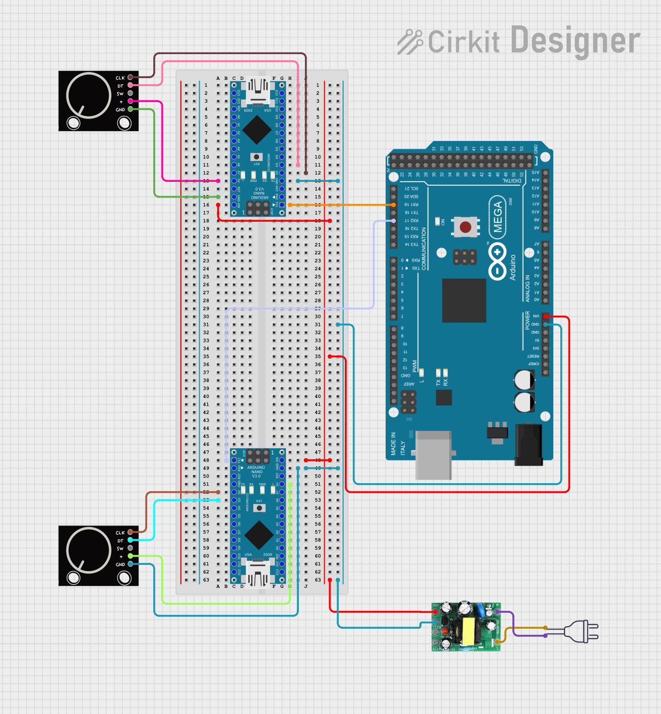
Circuit Documentation
Summary
This circuit involves multiple microcontrollers (Arduino Mega 2560 and Arduino Nano), rotary encoders, a power supply unit, and a 220V power source. The circuit is designed to interface rotary encoders with the microcontrollers, which are powered by an AC-DC PSU board converting 220V AC to 5V and 12V DC. The microcontrollers communicate with each other and the encoders to perform various tasks as defined in their respective code.
Component List
Rotary Encoder
- Description: A device that converts the angular position or motion of a shaft or axle to an analog or digital signal.
- Pins: GND, +, SW, DT, CLK
Arduino Mega 2560
- Description: A microcontroller board based on the ATmega2560. It has 54 digital I/O pins, 16 analog inputs, and 4 UARTs (hardware serial ports).
- Pins: IOREF, RESET, 3V3, 5V, GND, VIN, A0-A15, D21/SCL, D20/SDA, D19/RX1, D18/TX1, D17 PWM/RX2, D16 PWM/TX2, D15/RX3, D14/TX3, D0 RX0, D1 TX0, D2 PWM-D13 PWM, AREF, SDA, SCL, D52, D50, D48, D46, D44, D42, D40, D38, D36, D34, D32, D30, D28, D26, D24, D22, D53, D51, D49, D47, D45, D43, D41, D39, D37, D35, D33, D31, D29, D27, D25, D23
Arduino Nano
- Description: A small, complete, and breadboard-friendly board based on the ATmega328P.
- Pins: D1/TX, D0/RX, RESET, GND, D2-D13, VIN, 5V, A0-A7, AREF, 3V3
Power 220V
- Description: Standard 220V AC power source.
- Pins: Hot wire, Neutral wire
AC-DC PSU Board 220V-5V&12V
- Description: A power supply unit that converts 220V AC to 5V and 12V DC.
- Pins: AC-N, AC-L, +5V, GND, +12V
Wiring Details
Rotary Encoder 1
- GND connected to GND of Arduino Nano
- + connected to 5V of Arduino Nano
- DT connected to D3 of Arduino Nano
- CLK connected to D2 of Arduino Nano
Rotary Encoder 2
- GND connected to GND of Arduino Nano
- + connected to 5V of Arduino Nano
- DT connected to D3 of Arduino Nano
- CLK connected to D2 of Arduino Nano
Arduino Mega 2560
- GND connected to GND of AC-DC PSU board
- VIN connected to +5V of AC-DC PSU board
- D19/RX1 connected to D1/TX of Arduino Nano
- D17 PWM/RX2 connected to D1/TX of Arduino Nano
Arduino Nano 1
- GND connected to GND of AC-DC PSU board
- VIN connected to +5V of AC-DC PSU board
- D1/TX connected to D19/RX1 of Arduino Mega 2560
- D3 connected to DT of Rotary Encoder
- D2 connected to CLK of Rotary Encoder
- 5V connected to + of Rotary Encoder
Arduino Nano 2
- GND connected to GND of AC-DC PSU board
- VIN connected to +5V of AC-DC PSU board
- D1/TX connected to D17 PWM/RX2 of Arduino Mega 2560
- D3 connected to DT of Rotary Encoder
- D2 connected to CLK of Rotary Encoder
- 5V connected to + of Rotary Encoder
AC-DC PSU Board 220V-5V&12V
- AC-N connected to neutral wire of Power 220V
- AC-L connected to hot wire of Power 220V
- GND connected to GND of Arduino Mega 2560, Arduino Nano 1, and Arduino Nano 2
- +5V connected to VIN of Arduino Mega 2560, Arduino Nano 1, and Arduino Nano 2
Documented Code
Arduino Mega 2560 Code
void setup() {
  // put your setup code here, to run once:

}

void loop() {
  // put your main code here, to run repeatedly:

}
Arduino Nano 1 Code
void setup() {
  // put your setup code here, to run once:

}

void loop() {
  // put your main code here, to run repeatedly:

}
Arduino Nano 2 Code
void setup() {
  // put your setup code here, to run once:

}

void loop() {
  // put your main code here, to run repeatedly:

}
This documentation provides a comprehensive overview of the circuit, including a summary, detailed component list, wiring details, and the code for each microcontroller.