
Arduino-Controlled Bipolar Stepper Motor with 12V Battery Power
View and Edit Project In Cirkit Designer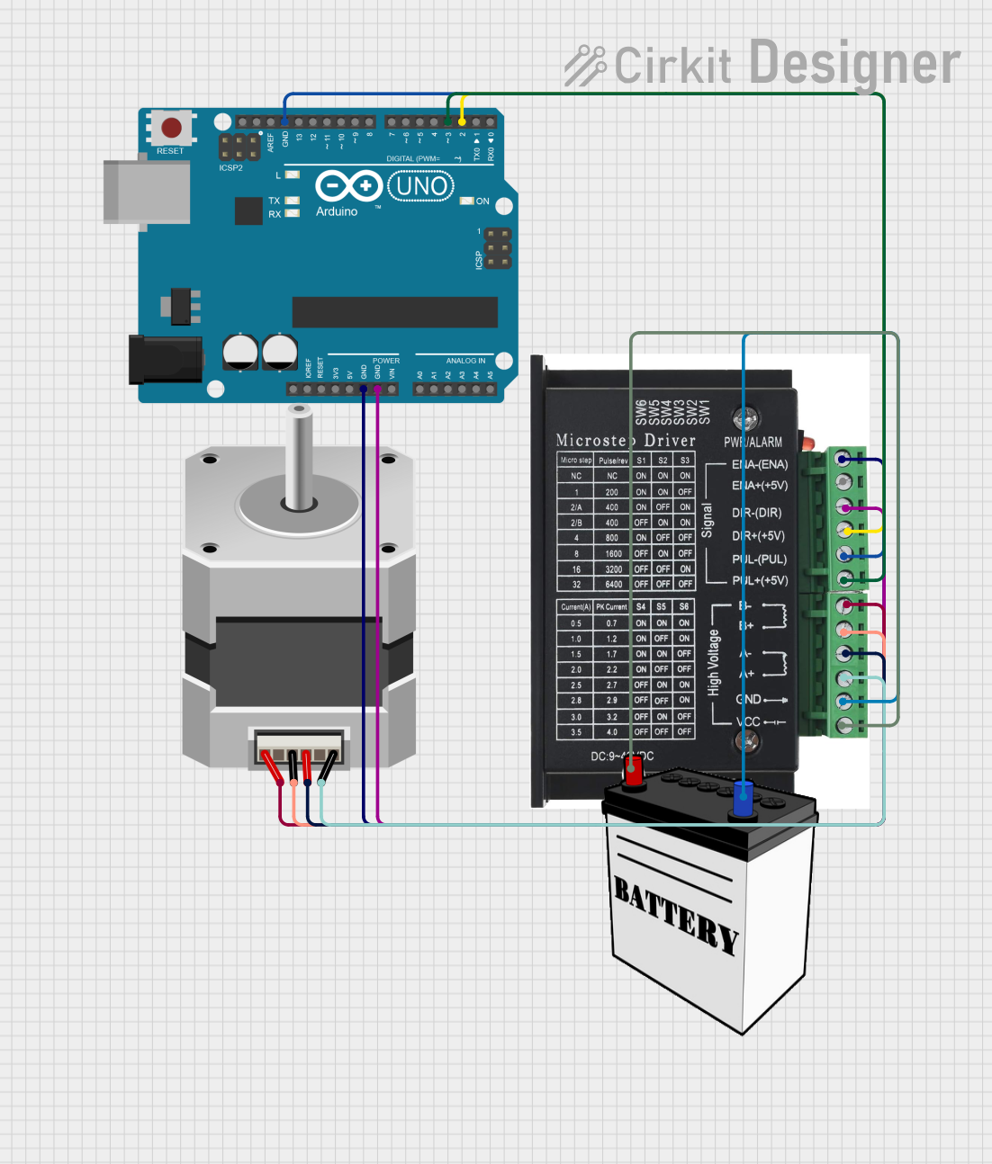
Circuit Documentation
Summary
This circuit is designed to control a bipolar stepper motor using an Arduino UNO microcontroller and a dedicated stepper motor driver. The Arduino UNO generates the necessary control signals (direction and step pulses) to the stepper driver, which in turn drives the stepper motor. The motor is powered by a 12V battery, which also supplies power to the stepper driver. The system is intended to rotate the stepper motor in precise increments, both clockwise and counterclockwise.
Component List
Arduino UNO
- Description: A microcontroller board based on the ATmega328P.
- Purpose: Generates control signals for the stepper motor driver and manages the sequence of motor steps.
- Pins: UNUSED, IOREF, Reset, 3.3V, 5V, GND, Vin, A0-A5, SCL, SDA, AREF, D0-D13.
Stepper Motor (Bipolar)
- Description: A bipolar stepper motor with four wires.
- Purpose: Executes the mechanical movements as instructed by the stepper driver.
- Pins: A, B, C, D.
STEPPER DRIVER
- Description: A driver module that controls the stepper motor.
- Purpose: Amplifies the control signals from the Arduino and drives the stepper motor.
- Pins: ENA -, ENA +, DIR -, DIR+, PUL -, PUL +, A-, A+, B-, B+, GND, VCC.
12V Battery
- Description: A 12-volt power source.
- Purpose: Provides power to the stepper motor and the stepper driver.
- Pins: VCC, GND.
Wiring Details
Arduino UNO
- GND connected to STEPPER DRIVER ENA -, DIR -, PUL -.
- D3 connected to STEPPER DRIVER PUL +.
- D2 connected to STEPPER DRIVER DIR+.
Stepper Motor (Bipolar)
- A connected to STEPPER DRIVER B-.
- B connected to STEPPER DRIVER A-.
- C connected to STEPPER DRIVER B+.
- D connected to STEPPER DRIVER A+.
STEPPER DRIVER
- GND connected to 12V Battery GND.
- VCC connected to 12V Battery VCC.
Documented Code
#include <AccelStepper.h>
#include <MultiStepper.h>

// Pin assignments
const int dirPin = 2;    // Direction pin
const int stepPin = 3;   // Pulse/Step pin
const int stepsPerRevolution = 200;  // For a 1.8-degree stepper motor (adjust as necessary)
const int stepsFor180Degrees = stepsPerRevolution / 2;  // 180 degrees = half of a full revolution

void setup() {
  // Set pins as outputs
  pinMode(stepPin, OUTPUT);
  pinMode(dirPin, OUTPUT);
}

void loop() {
  // Rotate motor clockwise 180 degrees
  digitalWrite(dirPin, HIGH);  // Set direction to clockwise
  for (int i = 0; i < stepsFor180Degrees; i++) {
    digitalWrite(stepPin, HIGH);
    delayMicroseconds(1000);  // Adjust delay for motor speed
    digitalWrite(stepPin, LOW);
    delayMicroseconds(1000);  // Adjust delay for motor speed
  }
  delay(1000);  // Pause for a second

  // Rotate motor counterclockwise 180 degrees
  digitalWrite(dirPin, LOW);  // Set direction to counterclockwise
  for (int i = 0; i < stepsFor180Degrees; i++) {
    digitalWrite(stepPin, HIGH);
    delayMicroseconds(1000);  // Adjust delay for motor speed
    digitalWrite(stepPin, LOW);
    delayMicroseconds(1000);  // Adjust delay for motor speed
  }
  delay(1000);  // Pause for a second
}
Filename: sketch.ino
Description: This code is designed to control a bipolar stepper motor via an Arduino UNO. It sets up the necessary digital pins as outputs and then enters a loop where it rotates the motor 180 degrees clockwise, waits for a second, then rotates it 180 degrees counterclockwise, and waits again. The delays between the steps can be adjusted to control the speed of the motor.