
Arduino UNO Controlled Ultrasonic Sensor with Dual Servo Output and I2C LCD Display
View and Edit Project In Cirkit Designer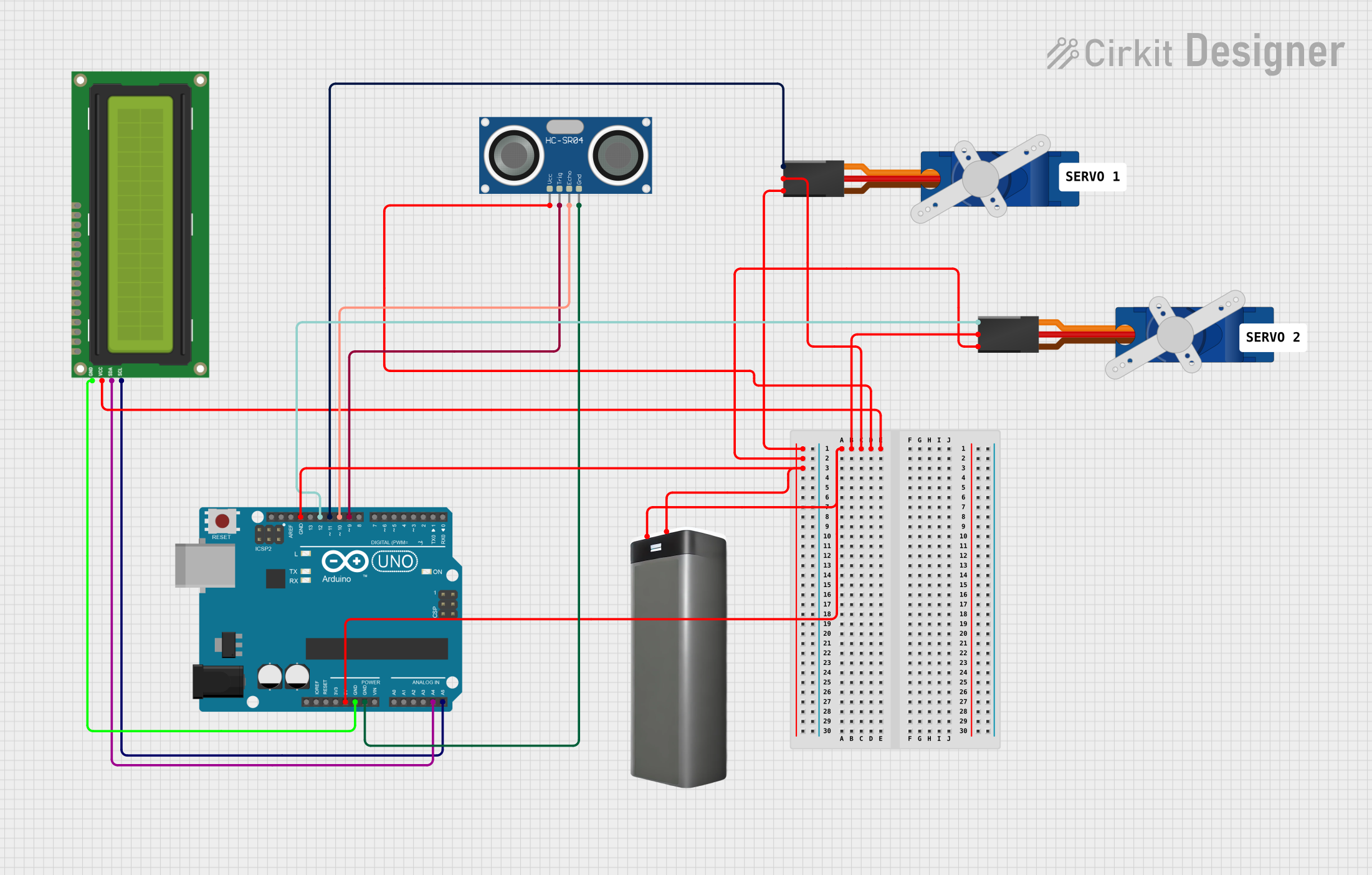
Circuit Documentation
Summary
The circuit in question is designed to interface an Arduino UNO with several peripheral devices, including an I2C LCD 16x2 screen, two Tower Pro SG90 servos, and an HC-SR04 ultrasonic sensor. The circuit is powered by a battery pack. The Arduino UNO serves as the central processing unit, controlling the servos and reading data from the ultrasonic sensor, with output displayed on the LCD screen. The communication with the LCD is done via the I2C protocol, utilizing the SDA and SCL lines.
Component List
Arduino UNO
- Microcontroller board based on the ATmega328P
- It has 14 digital input/output pins, 6 analog inputs, a 16 MHz quartz crystal, a USB connection, a power jack, an ICSP header, and a reset button.
I2C LCD 16x2 Screen
- A 16x2 character LCD display that uses the I2C communication protocol.
- It has pins for SCL, SDA, VCC, GND, and others for controlling the display.
HC-SR04 Ultrasonic Sensor
- A sensor that measures distance by emitting ultrasonic waves and measuring the time taken for the echo to return.
- It has pins for VCC, TRIG, ECHO, and GND.
Tower Pro SG90 Servo (x2)
- A small and lightweight servo motor capable of precise control.
- It has pins for Signal, +5V, and GND.
Battery Pack
- A power source for the circuit.
- It has pins for + (positive) and - (negative).
Wiring Details
Arduino UNO
- 5V and GND pins are used to power the board and the connected components.
- A4 (SDA) and A5 (SCL) are used for I2C communication with the LCD screen.
- D9 and D10 are used to control the TRIG and ECHO pins of the HC-SR04 ultrasonic sensor, respectively.
- D11 and D12 are used to send control signals to the Tower Pro SG90 servos.
I2C LCD 16x2 Screen
- SDA and SCL pins are connected to A4 and A5 on the Arduino UNO for I2C communication.
- VCC (5V) and GND are connected to the 5V and GND pins on the Arduino UNO for power.
HC-SR04 Ultrasonic Sensor
- VCC is connected to the 5V power supply net.
- TRIG is connected to D9 on the Arduino UNO.
- ECHO is connected to D10 on the Arduino UNO.
- GND is connected to the ground net.
Tower Pro SG90 Servo
- Signal pins are connected to D11 and D12 on the Arduino UNO for control signals.
- +5V pins are connected to the 5V power supply net.
- GND pins are connected to the ground net.
Battery Pack
-
- (positive) is connected to the 5V power supply net.
-
- (negative) is connected to the ground net.
Documented Code
void setup() {
  // put your setup code here, to run once:

}

void loop() {
  // put your main code here, to run repeatedly:

}
The provided code is a template with empty setup() and loop() functions, which are the entry points for Arduino sketches. The setup() function is called once when the sketch starts and is used for initializing settings, while the loop() function runs repeatedly, allowing the microcontroller to perform operations based on the logic defined within it. The actual implementation details need to be filled in based on the desired behavior of the circuit.